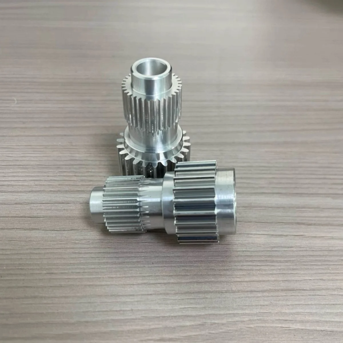
CNC-TURNED ALUMINUM PARTS · REPRESENTATIVE OF THIS BUILD
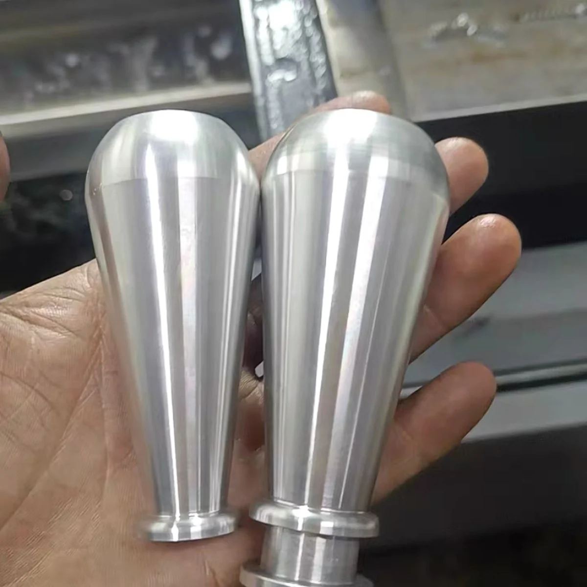
ALUMINUM · SINGLE-POINT TURNED ON CNC LATHE
The Brief
A client in the United Kingdom contacted us on WhatsApp about a custom two-part threaded connector — a male and a female component (we'll call them Part A and Part B) that thread together into a single assembly roughly 51 mm long. The mating thread was an imperial fine thread, 9/16"-18 UNF, with a Ø5 mm through-bore running the length of the assembly.
They didn't send a STEP file or a fully toleranced engineering drawing. They sent marked-up drawings with the key dimensions written on by hand — outer diameters, step lengths, the thread callout, the bore, and a 1 mm chamfer. That's a completely normal starting point for us; most first enquiries arrive exactly like this.
What we received: Annotated drawings of Part A and Part B with hand-written dimensions and an imperial fine-thread callout — no CAD file, no formal tolerance block. Enough for us to model it and come back with the questions that matter.
Step 1 — CAD Redraw the Same Day
As soon as the dimensions came in, our engineer rebuilt both parts as a full 3D CAD model and a clean 2D drawing. Redrawing in CAD does two things: it gives the client a precise drawing to sign off against, and it surfaces anything that's ambiguous or won't function before a single chip is cut. For this connector the points that needed locking down were:
- The 9/16"-18 UNF thread class and engagement length, so Part A and Part B actually mate cleanly
- The fit between the spigot diameter (~Ø14.5) and its mating bore — turned to a controlled tolerance, not a nominal number
- The Ø5 mm through-bore concentric to the OD along the full 51 mm
- The 1 mm lead-in chamfer for easy thread start and assembly
Step 2 — The Revision Loop (Part B)
After reviewing our CAD, the client came back with one change: a single length dimension on Part B needed to be adjusted. This is exactly why we redraw and confirm before machining — catching it on the drawing costs five minutes; catching it on a finished batch costs a remake.
We updated the model, re-issued the full revised drawing of the assembly, and asked the client to check Part B specifically. The reply came back: "All confirmed, Part B is OK." With the geometry signed off, we moved to a proforma invoice and delivery details.
Why this matters: A back-and-forth of one or two key dimensions on the drawing is normal and good — it means the part that ships is the part the customer actually wants. We don't start cutting metal until the drawing is confirmed in writing.
Step 3 — Machining
A two-part threaded connector like this is primarily a CNC turning job, with thread turning and cross-drilling as needed. Typical sequence for each part:
- Turn the profile: Bar stock turned to the stepped outer diameters and faced to length. Critical fit diameters held to a controlled tolerance, not just nominal.
- Drill the through-bore: Ø5 mm bore drilled and reamed concentric to the OD along the full length.
- Cut the 9/16"-18 UNF thread: Single-point turned (or die/tap for the mating part), then checked with a thread ring/plug gauge so Part A and Part B assemble correctly.
- Chamfer & deburr: 1 mm lead-in chamfer and full deburr for clean assembly.
- Trial assembly & inspect: Part A threaded into Part B to confirm fit, then key dimensions measured and recorded.
TWO-PART ASSEMBLY · TRIAL-FITTED BEFORE SHIPMENT
Ø5 THROUGH-BORE · CONCENTRIC TO OD
9/16-18 UNF · THREAD-GAUGE VERIFIED
Step 4 — Inspection
Key features were checked before the parts were packed:
| Feature | Spec | Method |
|---|---|---|
| Mating thread | 9/16"-18 UNF | Thread ring / plug gauge |
| Spigot fit diameter | ~Ø14.5 (controlled) | Micrometer |
| Through-bore | Ø5mm | Plug gauge |
| Overall length | ~51mm assembled | Caliper / CMM |
| Assembly fit | Part A + Part B mate cleanly | Trial assembly |
Project Timeline
Enquiry & drawings received
Client sent marked-up drawings of Part A and Part B over WhatsApp with hand-written dimensions and the 9/16"-18 UNF thread callout.
CAD redraw & key-dimension questions
We rebuilt both parts in CAD and confirmed the critical fits, thread, and bore — sending back a clean drawing for review.
Part B revision & sign-off
Client requested one length change on Part B. We updated the model, re-issued the full drawing, and the client confirmed: "All confirmed, Part B is OK."
Proforma invoice & delivery details
With geometry locked, we prepared the PI and collected delivery details to schedule production and shipping.
Turning, threading & inspection
Both parts CNC-turned, threads gauge-checked, trial-assembled, and key dimensions recorded before packing.
Outcome
From a set of hand-marked drawings to a confirmed, production-ready design — including a real revision on Part B — without the client ever needing to supply a CAD file. The free CAD redraw and the dimension-confirmation loop are what make ordering from a sketch or a marked-up drawing low-risk: the client signs off on a precise drawing, and only then do we cut metal.
Have a part like this? Send your drawing, a marked-up sketch, or a photo of an existing part — even just the key dimensions and the thread. We'll redraw it in CAD, confirm the critical fits with you, and quote. Email [email protected] or message us on WhatsApp.