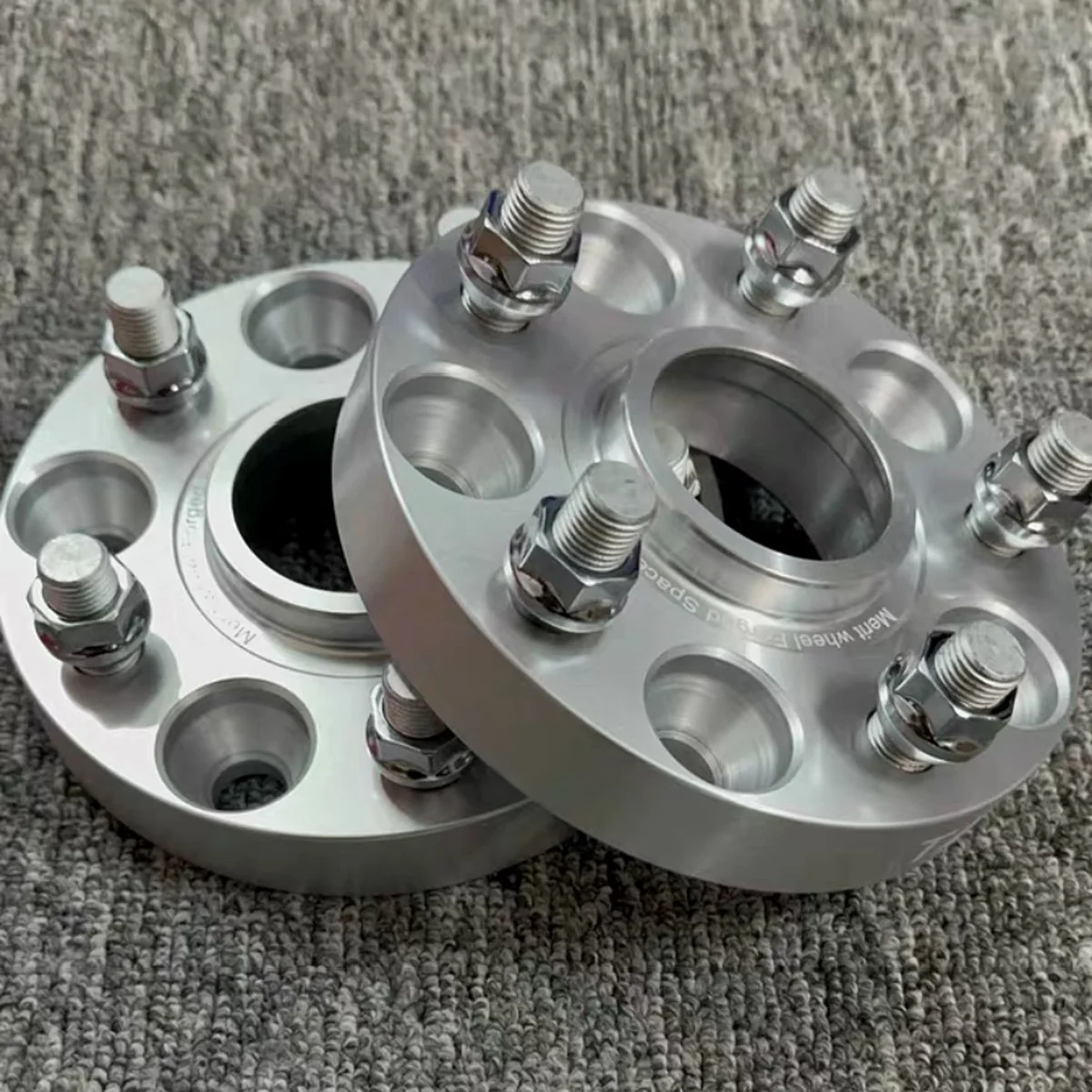
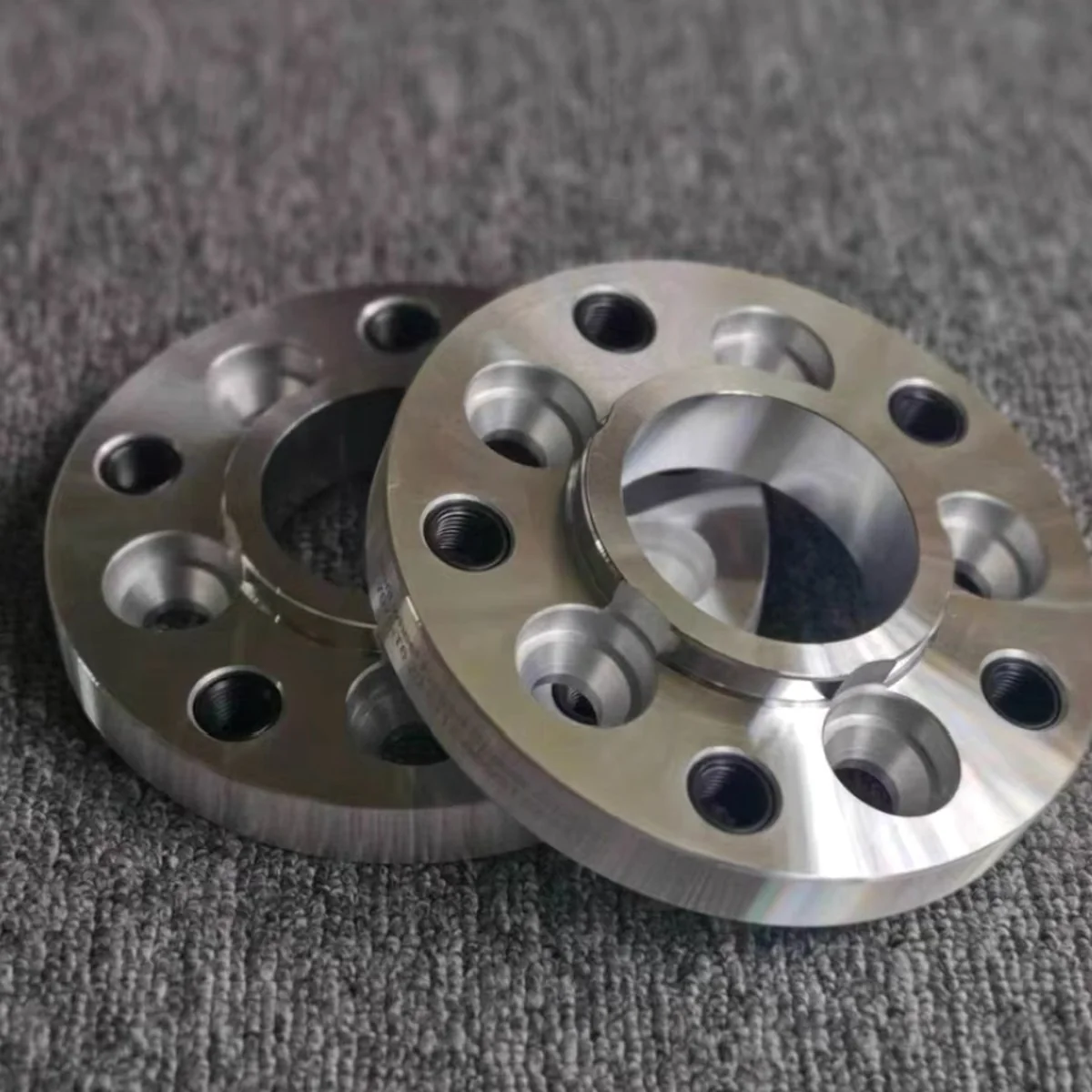
FINISHED AL 7075-T6 WHEEL SPACERS · AS-MACHINED SILVER FINISH
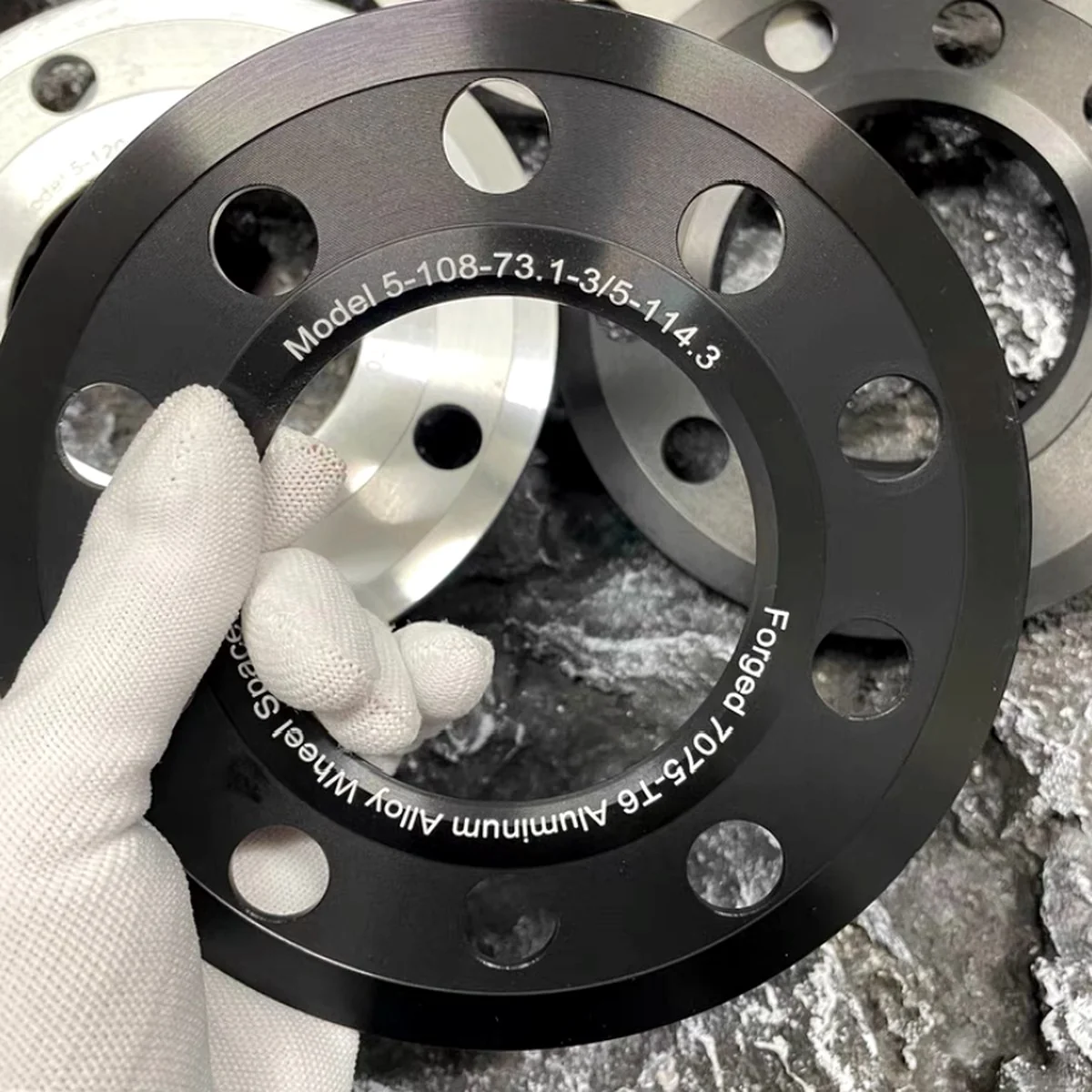
BLACK ANODIZED VERSION · PCD AND HUB BORE LASER MARKED
The Brief
A UK motorsport parts supplier contacted us needing a custom set of wheel spacers for a track-day vehicle build. Their customer had a specific bolt pattern and hub bore combination that wasn't available off-the-shelf — 5×10⁸ bolt pattern with a 73.1mm hub bore and 25mm thickness, in both silver and black anodized finishes.
They didn't have a CAD file. They sent a hand-drawn sketch with the critical dimensions written in pencil — bolt circle diameter, hub bore, overall thickness, and stud hole diameter. No tolerances specified on the drawing beyond "needs to fit properly."
What we received: A photo of a hand-drawn sketch on A4 paper with approximate dimensions. No CAD file, no tolerance callouts beyond the critical bore and PCD dimensions. This is a typical starting point for many of our orders.
Material Selection: Why 7075-T6
Wheel spacers are safety-critical components. They carry the full lateral and vertical loads of a moving vehicle. Material choice matters significantly:
| Property | Al 6061-T6 | Al 7075-T6 | Why it matters |
|---|---|---|---|
| Tensile Strength | 310 MPa | 572 MPa | Higher strength under wheel loads |
| Yield Strength | 276 MPa | 503 MPa | Resists deformation under clamping torque |
| Density | 2.70 g/cm³ | 2.81 g/cm³ | Minimal weight difference vs. big strength gain |
| Machinability | Excellent | Good | Slightly harder to machine, tools wear faster |
| Anodizing | Excellent | Good | Takes anodize well, slightly darker natural colour |
| Typical use | General structural | Aerospace, motorsport | Higher safety margin for load-bearing parts |
We recommended 7075-T6 over the more common 6061. The customer confirmed — the extra strength margin was appropriate for a track-day application where wheel loads are higher than road use.
CAD Redraw Process
Our engineer received the sketch photo at 09:30. By 14:00 the same day, we had a full 3D CAD model in STEP format ready for customer review. The model included:
- Hub bore diameter to H7 tolerance (interference fit with hub spigot)
- 5× stud holes on 108mm PCD — bolt circle accuracy ±0.05mm
- Chamfered stud hole entries for easier fitment
- Flat faces parallel within 0.02mm (critical for wheel seating)
- Laser engraving position for PCD/hub bore marking
The customer reviewed the STEP file in their CAD viewer, confirmed the geometry, and approved production the same afternoon.
Machining
Wheel spacers are primarily a CNC turning job with secondary milling for the stud holes. The process sequence:
- Op 1 — Turn OD and face: Billet 7075-T6 bar turned to outer diameter, face skimmed flat. Hub bore rough bored.
- Op 2 — Finish bore hub: Hub bore finish bored to H7 tolerance. Surface finish Ra 1.6μm for good hub register fit.
- Op 3 — Mill stud holes: 5× stud holes drilled and reamed on CNC mill. PCD accuracy held to ±0.05mm using rotary table.
- Op 4 — Deburr and inspect: All edges deburred. Hub bore, OD, thickness, and PCD measured and recorded.
- Op 5 — Anodize: Silver parts clear anodized (Type II, 15μm). Black parts black anodized. Both batches to same dimensional spec — anodize layer accounted for in final machined dimensions.
- Op 6 — Laser mark: PCD and hub bore specifications laser engraved on face for customer identification.
SILVER · AL 7075-T6 · AS-MACHINED
PRECISION FACE · FLAT WITHIN 0.02mm
BLACK ANODIZED · LASER MARKED
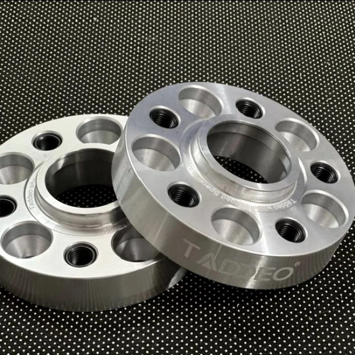
SILVER ANODIZED · CUSTOMER BRANDING
Technical Challenges
Hub bore tolerance: The H7 tolerance on the hub bore (±0.015mm) is the most critical dimension. Too loose and the spacer doesn't register accurately on the hub. Too tight and it won't fit. We bore this in two passes — rough bore leaving 0.15mm stock, then finish bore to final dimension with a dedicated boring head. CMM verification after each batch.
PCD accuracy: The stud holes must be precisely on the bolt circle diameter. A 5-stud spacer with one hole out of position won't accept all five wheel bolts. We hold PCD accuracy to ±0.05mm using a precision rotary table on the mill.
Anodize dimensional allowance: Type II anodize builds approximately 5–8μm per side. Black anodize builds 15–20μm. We machine final dimensions with this allowance factored in so the anodized part hits the target dimension — not the pre-anodize dimension.
Inspection & Quality
Every wheel spacer in this batch was inspected before shipment:
| Dimension | Nominal | Tolerance | Method |
|---|---|---|---|
| Hub bore diameter | 73.1mm | H7 (+0.000/+0.030mm) | Bore gauge + CMM |
| Overall thickness | 25.0mm | ±0.05mm | Outside micrometer |
| Stud PCD | 108.0mm | ±0.05mm | CMM |
| Stud hole diameter | 14.3mm | +0.1/0mm | Plug gauge |
| Face flatness | — | 0.02mm | CMM |
| Face parallelism | — | 0.02mm | CMM |
Project Timeline
AM
Sketch received — CAD redraw begins
Hand sketch photo received by email at 09:30. Engineer reviewed dimensions, identified the hub bore as critical H7 fit, began 3D model.
PM
CAD model sent — customer approves
STEP file and 2D drawing sent to customer at 14:00. Customer confirmed geometry and approved production at 16:30 same day. NDA signed, 50% deposit paid.
Turning, milling, deburring, inspection
Material cut from 7075-T6 bar stock. Turning completed for OD and hub bore. Mill ops for 5× stud holes. 100% dimensional inspection on CMM. All parts passed.
Anodizing and laser marking
Parts sent to anodize supplier. Clear (silver) Type II anodize on one batch, black anodize on second. Returned and laser marked with PCD/hub spec. Post-anodize dimension check confirms within spec.
Packing and dispatch
Parts individually wrapped, placed in foam tray, packed in outer carton. Packing photos sent to customer. DHL Express shipment dispatched. Tracking number provided same day.
Delivered — customer confirms fit
DHL delivered to UK. Customer fitted same day. Hub bore registered correctly on the vehicle. All stud holes accepted bolts without issues. Customer confirmed ready for their next order.
Outcome
Twelve days from pencil sketch to parts on the car. The customer had tried two other suppliers before reaching us — one required a CAD file and the other had an 8-week lead time. We accepted the hand drawing, redrawed it in CAD within half a day, and delivered finished anodized parts faster than most suppliers can acknowledge a quote request.
The same customer has since ordered three more custom wheel spacer configurations — different PCD patterns and thicknesses — all from hand sketches or simple PDF drawings.
Have a similar project? Send us your sketch — bolt pattern, hub bore, thickness, and quantity is all we need to start. We'll have a CAD model back to you the same day and parts machined within two weeks. Email [email protected] or message us on WhatsApp.