// Fanless · passive cooling · housing and heatsink in one piece
Custom Aluminum Heatsink Enclosures — CNC Machined Around Your Board
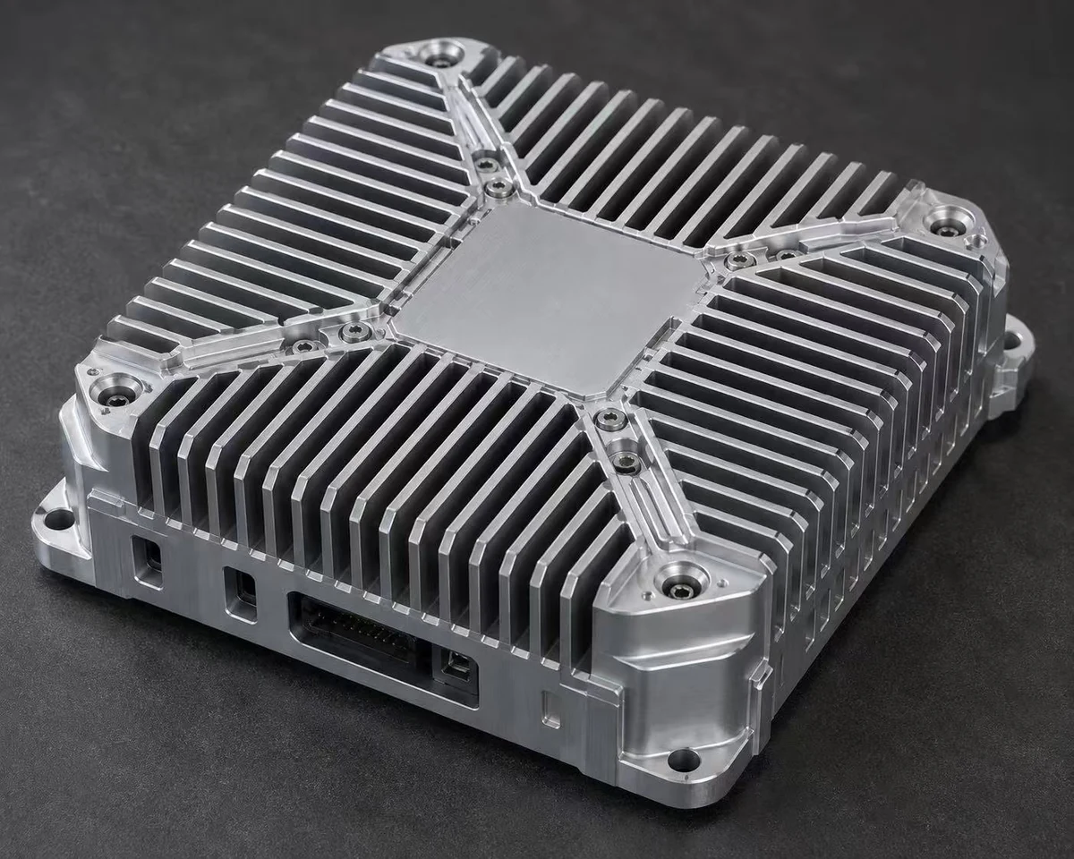
The housing is the heatsink: fin field over the processor, connector cut-outs, standoffs and sealing machined from one block of aluminum. For the enclosure your edge AI computer, robot controller or embedded PC Needs — not the closest catalogue box.
[✓]Machined around your PCB — from STEP, Gerber, or the board itself
[✓]Fanless — no vents, no moving parts, IP65/IP67 possible
Looking for someone to machine a heatsink enclosure to your design — or to design one around your board? Send the STEP file, or just the PCB and the component powers. Drawing for approval before machining, from one piece, quote in 12 hours.
Why the housing and the heatsink should be one part
A separate heatsink bolted to a box adds two thermal joints, a stack of tolerances and an assembly step. Machining the fins into the enclosure wall removes all three: heat crosses one interface — the thermal pad between processor and pedestal — and then it is already in the fin field. The same block gives you EMI shielding, structural mounting and, with an O-ring groove in the cover joint, IP65/IP67 sealing with zero vents.
That is why fanless edge computers, robot controllers and outdoor AI boxes are built this way. The catch is that the fin field, pedestal and cut-outs are specific to your board — which is exactly the part a catalogue enclosure cannot give you, and the part we machine.
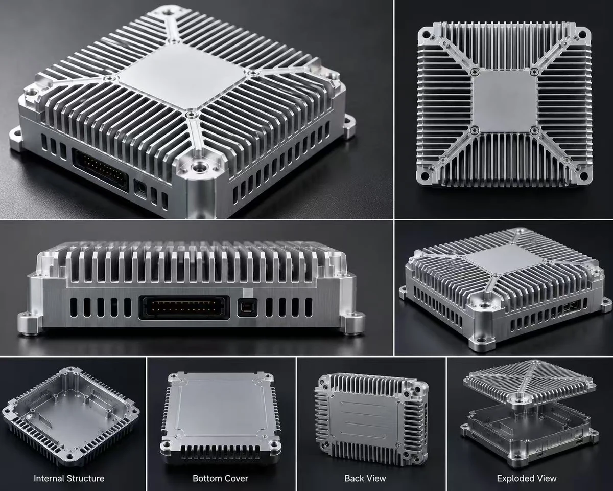
A recent build — internal cavity, bottom cover, connector panel and exploded view. Fin field and cut-outs are yours, not a catalogue's
CNC billet or extrusion — the honest decision table
CNC from 6061-T6 billet
Extruded 6063-T5 profile + CNC
Fin geometry
Any — pin fins, radial, variable pitch, fins over the hot spot only
Straight fins fixed by the die, one direction
Tooling cost
None — prototype = production
Profile die required
Sensible quantity
1 – ~500 pcs
From a few hundred pcs
Thermal conductivity
≈167 W/m·K
≈200 W/m·K
Strength (bosses, threads)
Higher — T6 billet
Softer alloy
Wall / cavity freedom
Full 3D — pockets, pedestals, variable walls
Constant cross-section, then machined
The practical rule: prototypes and volumes up to a few hundred are billet CNC; sustained volumes justify a die and move to extrusion with CNC finishing. We quote both when the quantity is near the boundary, so you see the crossover price instead of guessing. Where strength matters more than heat — a bracket, not a heatsink — 7075-T6 is available; where corrosion or washdown dominates, a 304 stainless enclosure without fins is the honest answer and we will say so.
Where these enclosures go
// Edge AI
Edge AI computer & AI processor enclosures
High-TDP modules in a sealed, fanless box — pedestal over the SoC, fin area sized to the real power draw, black anodize for radiation.
// Jetson
NVIDIA Jetson carrier enclosures
Orin / Xavier class carrier boards: thermal transfer plate matched to the module TTP, cut-outs for your I/O rather than the devkit's.
// Robotics
Robot, AGV & AMR controller housings
Vibration-rated mounting feet, M12 connector panels, IP65 against dust and washdown — no fan to fail mid-shift.
// UAV
Drone flight controller & UAV computer housings
Weight-critical: thin-wall pockets, fins only where the heat is, every gram machined away that the thermals allow.
// Industrial
Embedded & industrial PC enclosures
DIN-rail or panel mount, 100×100 / 120×120 / 150×150 footprints, cable glands and IP67 where the cabinet is outdoors.
// Vision
Vision AI & camera processor housings
Sealed against dust with the processor heat still out through the shell — lens opening and mount machined to your optics.
What we machine into the enclosure
Thermal pedestal — raised contact pad over the processor, height set to your component stack with the thermal pad gap you specify
Fin field — straight, pin or radial; pitch and height sized to the power and the mounting orientation, not copied from a catalogue
Connector cut-outs — machined to your I/O panel, not punched approximations; countersunk and deburred
Standoffs and bosses — tapped in the housing itself, positioned from your board data
O-ring groove — in the cover joint for IP65/IP67, with the gasket specified for the temperature range
Finish — anodize clear or black (black helps passive dissipation), bead blast, laser-engraved markings
Where a catalogue enclosure profile runs out
Fischer Elektronik and Alutronic stock extruded profiles deep, in fixed cross sections you cut to length. That covers a lot of jobs. It stops where your board stops fitting somebody else's cross section.
What your board needs
In the catalogue?
What we do about it
Cavity to your board outline — 120 × 120 mm with a clipped corner, wall thick where the mounting feet load it
Only if the board fits between the profile's fixed inner walls. The cross-section is the die's; you choose the length, nothing else
Cavity milled to the outline, wall thickness set where you need it instead of where the die left it
Connector cut-outs on your I/O face — your stack, M12 glands, an odd-height header
Not from the profile. The die makes the cross section; every opening on the I/O face is a second operation on top of the extrusion
Openings cut from your DXF or Gerber panel data in the same setup as the cavity, so panel and board share one datum
Standoffs at your board's hole pattern, tapped into the enclosure floor
No — a constant section has no floor features. Standoffs are separate parts you screw, press or bond in
Bosses milled and tapped from the same board file as the cavity — one part to inspect instead of six
Fin field only over the 25 W SoC, shell flat elsewhere for the label and the DIN-rail clip
No — one constant cross-section, so the fins run the full length in one direction whether the heat is there or not
Fins cut where the heat is; the rest of the shell stays flat, and the removed metal comes off the shipping weight
Copper under a concentrated hot spot — spreading before the heat reaches the fins
No — a profile is one aluminum alloy end to end
C11000 pedestal insert (about 388 W/m·K) into a machined pocket in the 6061-T6 wall. It costs weight: 8.96 g/cm³ against 2.70
Fins 0.6 mm thick, 20 mm tall (33:1) directly over the processor
No — extruded profiles reach about 12:1, from about 1.20 mm, with 1–2° draft per side
Not millable into the wall either: milled fins run out near 8:1, from about 1.00 mm. Below 8:1 the fins are cut into the wall and there is no joint at all. Above it the fin field stops being part of the housing: machined base, 0.30–1.00 mm rolled fins bonded in, up to 50:1, no tooling, from 1 piece. That buys aspect ratio and costs you one bonded joint — worth it only when 8:1 is not enough
A plain finned box — 100 × 160 mm, straight fins, no sealing, openings only on the end plates, 300 pcs
Yes. Stocked profile, cut to length, end plates drilled
Buy it off the shelf. At that spec we would machine what is already on a shelf, charge more for it, and ship later than the distributor
A 5 W board that needs sealing, not cooling — IP65, no fin field
Yes — a stock sealed box in a standard size
Buy it, and bolt a catalogue heatsink to the lid if it runs warm. Two shelf parts and four screws beat one machined part until the seal and the fin field have to be the same piece of metal
When not to ask us: if your board fits inside a stocked cross-section, the only openings are on the end plates, and straight fins running the full length are good enough thermally, then a stocked profile cut to length is cheaper in the catalogue than anything we can machine, and it ships from a distributor's shelf. Send us the job when the board outline, the cut-outs and the pedestal have to be one piece of metal, or when the quantity is 1 to a few hundred and no die exists. Send the drawing either way — if the honest answer is the catalogue part, that is what we will write back inside 12 hours.
Send what you have — CAD or not
You have
What happens
STEP / STP / SolidWorks
Straight to CAM — quote and lead time in 12 h
DXF + Gerber / PCB data
We build the enclosure model around the board outline and component map
PDF drawing
Redrawn as a 3D model, submitted for your approval
Tell us the board size, component powers and environment — we design it, you approve the drawing before machining
On "can you improve the cooling": usually yes — fin area, pitch, base thickness under the hot spot, pad contact and black anodize are real levers. But we quote improvements from your component powers, not from optimism. If the physics says the box is already at its passive limit, we tell you that too.
Frequently asked questions
Yes — housing and heatsink machined as one piece: fin field over the thermal pad, connector cut-outs, standoffs and a machined bottom cover, from 6061-T6 billet or a 6063-T5 extruded profile, anodized clear or black. Send a STEP file or the PCB and we take it from there.
Yes. Send the PCB as STEP, or DXF outline plus Gerbers, and mark the hot components with their powers. The pedestal lands exactly over the processor, standoffs and openings come from the board data, and you approve the dimensioned drawing before machining.
Often, within honest physics: fin area, fin pitch, base thickness, pad contact and black anodizing are the levers. Send the current model and component powers — we tell you which changes are worth machining and what they realistically buy, with numbers rather than promises.
Yes, 6061-T6 is the billet default (≈167 W/m·K, strong, anodizes well). Extrusions use 6063-T5 (≈200 W/m·K, softer). 7075-T6 where strength beats heat; copper pedestal inserts for concentrated hot spots; 304 stainless where the environment, not the processor, is the problem.
Yes — fanless is the point: no vents, no moving parts. For IP65/IP67 we machine an O-ring groove into the cover joint and use sealed glands or M12 connectors at the I/O. State the rating and the environment; the gasket is specified to match.
STEP/STP goes straight to CAM. SolidWorks, DXF, PDF, Gerber, a sample, or no CAD at all also work — in the no-CAD case we design around your board and you approve the drawing first. Quote in 12 hours either way.
One piece, no tooling cost, for CNC billet — prototype and production run from the same file. Extrusion-based versions make sense from a few hundred pieces because of the die; below that, billet wins and we quote it that way. Price breaks at 1 / 10 / 50 / 200.
Send Your Files
STEP, Gerber, PDF or just the board size and component powers. Engineers reply in 12 hours.