What Is a Flexible PCB (FPC)?
A flexible PCB (FPC, flex circuit) is a printed circuit on a thin polyimide film that bends to fit a product: it replaces cables between boards and carries antennas, sensors, heaters and connectors where a rigid board does not fit.
EKINSUN is a custom parts manufacturer in China that makes flexible PCBs and rigid-flex boards from one piece, bare or assembled, and carries them into production. What sets this apart: the flex circuit, the rigid boards, the enclosure and the assembled device come from one supplier.
Single-Sided, Double-Sided, Multilayer or Rigid-Flex?
| Type | What it is | Typical use |
|---|---|---|
| Single-sided FPC | One copper layer on polyimide, with coverlay | Simple connections, coils, heaters |
| Double-sided FPC | Two copper layers joined by plated holes | Connections with crossing traces, small components |
| Multilayer FPC | Three or more copper layers | Dense routing, controlled impedance |
| Rigid-flex | Rigid sections joined by flexible layers in one board | Products that fold, with no connectors between boards |
| HDI flex | Blind and buried vias, fine lines | Small high-density products |
Flexible PCB Capabilities
The standard column is what every order can use; the second column is made after your files are evaluated, as high-difficulty flex and rigid-flex always are.
| Item | Standard | On evaluation (from your files) |
|---|---|---|
| Board types | Single-sided, double-sided, multilayer FPC; rigid-flex | Air-gap (separated-layer) flex, HDI with blind and buried vias, special builds |
| Layers | 1–4 | FPC up to 30; rigid-flex and HDI 2–32 |
| Board / panel size | up to 250 × 1200 mm | up to 500 × 1000 mm |
| FPC thickness | 0.07–0.235 mm | 0.06–0.4 mm; rigid-flex 0.25–6.0 mm |
| Thickness tolerance | ±0.03 mm (0.07 mm board), ±0.05 mm (0.3 mm board) | ±0.03 mm |
| Min. line / space | 0.07 / 0.07 mm | 0.025 / 0.025 mm |
| Min. drill | 0.15 mm | 0.1 mm |
| Hole tolerance (plated and non-plated) | ±0.05 mm | ±0.05 mm |
| Copper | 1/3–2 oz (12, 18, 35, 70 µm) | 1/4–3 oz |
| Coverlay / insulation | 27.5 µm, 50 µm | 75, 100, 125, 150 µm |
| Solder mask thickness | 7.5–20 µm | 30 µm |
| Solder mask registration | ±0.1 mm | ±0.075 mm |
| Coverlay alignment (hand / fixture) | ±0.3 / ±0.2 mm | ±0.2 / ±0.15 mm |
| Min. castellated (half) hole, punched slot | 0.4 mm, 0.8 mm | — |
| Impedance control | 50–120 Ω, ±10 % | — |
| Stiffeners | FR4, PI, PET, stainless steel (SUS), PSA adhesive | — |
| Standards | IPC-6013 Class II and Class III, IPC-TM-650 test methods | — |
How Long Does a Flexible PCB Take?
A flexible PCB prototype takes 3–4 days single-sided, 4–5 days double-sided, 6–7 days multilayer and 8–10 days rigid-flex, with express in 24–48 hours.
| Type | Prototype | Batch |
|---|---|---|
| Single-sided FPC | 3–4 days | 5–6 days |
| Double-sided FPC | 4–5 days | 7–8 days |
| Multilayer FPC | 6–7 days | 8–10 days |
| Rigid-flex | 8–10 days | 8–12 days |
| Express | 24–48 hours | 3 days (small batch) |
Stiffeners and Surface Finish
A stiffener is a rigid layer bonded behind part of a flex circuit: under components and connectors so the solder joints do not flex, and at a connector tail to set the thickness the connector needs. Stiffeners are FR4, PI, PET or stainless steel, bonded with PSA adhesive where the part is fixed into the product.
- ENIG (immersion gold): gold 0.025–0.075 µm over nickel 1–4 µm, flat pads for fine-pitch parts.
- Hard gold plating: 3–100 µin (about 0.08–2.5 µm) for contacts and fingers that are plugged.
- OSP: 0.2–0.8 µm organic coating; also immersion silver and tin.
What We Make on Flex
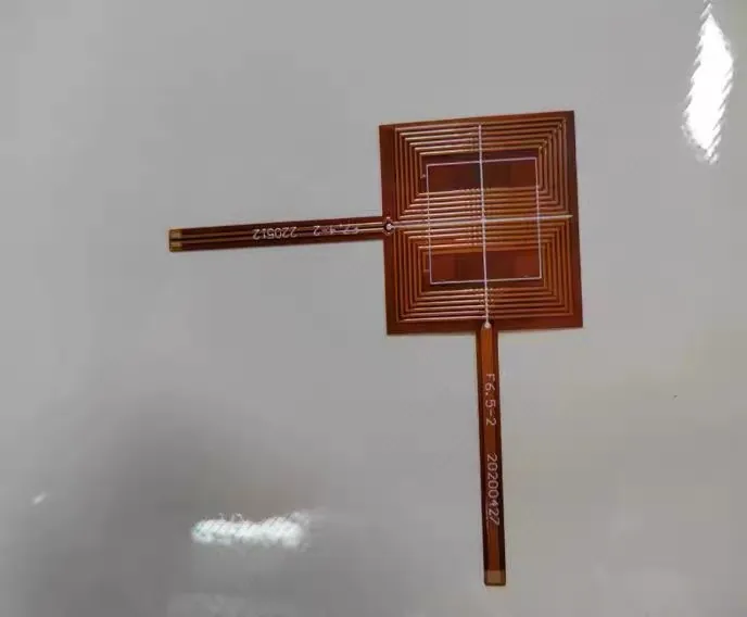
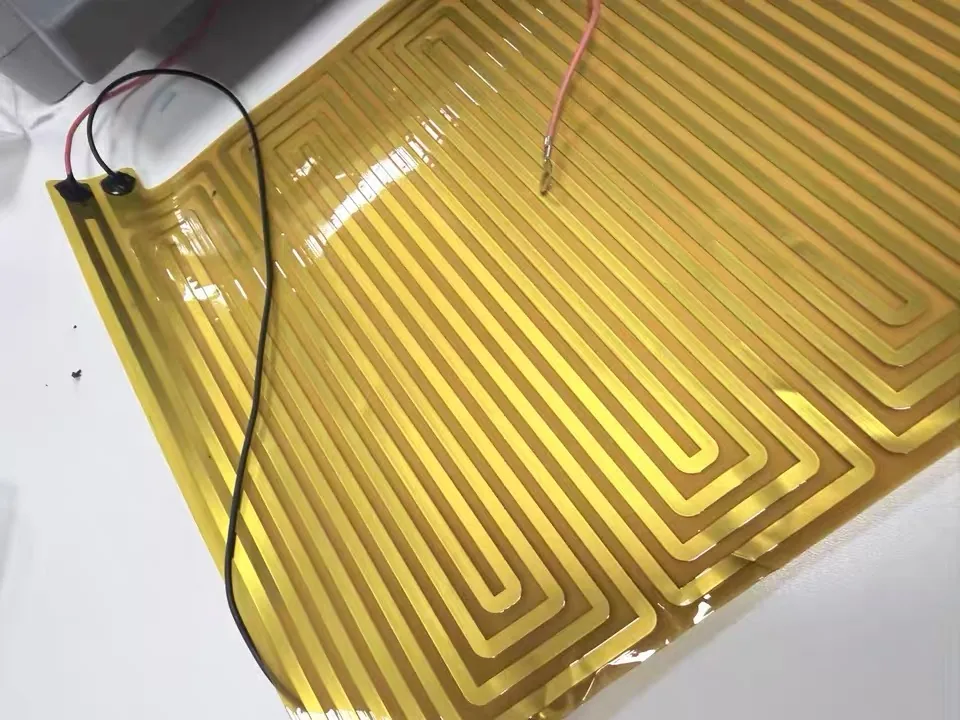
Flex circuits made here include cables between boards with connectors, planar coils and polyimide heaters.
Files for a Flexible PCB
- Gerber files with the board outline, every copper layer, the coverlay openings and the drill file.
- Stack-up: layer count, copper thickness, coverlay and the bend areas.
- Stiffener drawing: location, material and thickness of every stiffener.
- BOM and pick-and-place file if the flex is assembled.
Every order starts with a check of the files. Send them to [email protected].
Standard Flat Cable or Custom Flex
| What you need | In the catalogue? | At EKINSUN |
|---|---|---|
| Flat flexible cable (FFC) at a standard pitch and length | Stocked by length and pitch. | Buy it there, or ask us, we quote it with the rest of your build. |
| A flex circuit in your own shape, with your routing | Not a catalogue item. | Made from your Gerber files from 1 piece. |
| Flex with components or connectors | — | Assembled with stiffeners; the rigid boards beside it: PCB assembly. |
| The whole device | — | Box build assembly from 1 unit. |
PCB and electronics: PCB assembly (PCBA), box build assembly, PCB mounting hole chart, custom enclosures, NDA, Deutsch, Français, Italiano, Español
Frequently Asked Questions
A flexible PCB (FPC, flex circuit) is a printed circuit on a thin polyimide film that bends to fit a product; it replaces cables between boards and carries antennas, sensors, heaters and connectors where a rigid board does not fit.
An FPC is a custom flexible circuit made to your Gerber files, with any shape, routing and components; an FFC (flat flexible cable) is a standard ribbon of parallel conductors at a fixed pitch, bought by length and pitch.
Flexible PCBs are made with 1 to 4 layers as standard; multilayer flex up to 30 layers and rigid-flex and HDI boards with 2 to 32 layers are made after the files are evaluated.
A standard flexible PCB is 0.07 to 0.235 mm thick, and 0.06 to 0.4 mm is possible on evaluation; rigid-flex boards are 0.25 to 6.0 mm thick.
EKINSUN makes flexible PCBs from 1 piece; prototypes and batches are built from the same files.
A flexible PCB prototype takes 3–4 days single-sided, 4–5 days double-sided, 6–7 days multilayer and 8–10 days rigid-flex, with express in 24–48 hours; batches take 5–12 days by type.
Yes, EKINSUN assembles components on flex circuits; the area under components and connectors is usually backed with a stiffener (FR4, PI, PET or stainless steel) so the solder joints do not flex.
Yes, EKINSUN makes rigid-flex boards, where rigid sections are joined by flexible layers built into the same board, 0.25 to 6.0 mm thick and 2 to 32 layers after evaluation.
A flexible PCB needs Gerber files with the board outline, the coverlay openings and the stack-up, plus a stiffener drawing with location, material and thickness; add the BOM and pick-and-place file if it is to be assembled.
Send Your Flex Files for a Quote
Layers, thickness, stiffeners, quantity and whether it is assembled; Gerber files by email to [email protected].
Quantity
1 unit
Prototype
Prove the design
A few
Test builds
Field and lab units
Batch
Production
Same files
- Flex prototypes from 3–4 days
- NDA before files, the design stays yours
From 1 unit, Files confidential