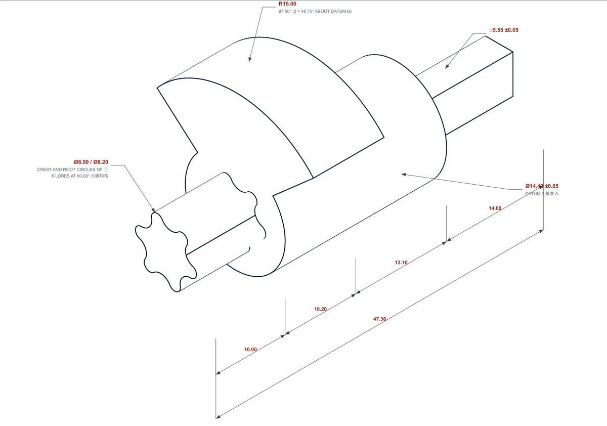
DETAIL FROM THE RELEASED DRAWING · FOUR FEATURES ON ONE 47.30 MM AXIS · CUSTOMER-CONFIRMED VALUES IN RED
A contact in the UK asked a short question: can you take on complex parts — the kind where one piece needs several different processes? That question is better answered with a part than with a paragraph, so here is one. It is not their part. It is a separate job, run in August 2026 for a different customer, and it is used here because it puts four unrelated features on a single 47.30 mm axis, and because the CAD file it arrived with could not be made as drawn.
Two things are worth separating before the detail. Machining four features is a capacity question. Deciding what the four features are, when the file does not say, is an engineering question — and that is the part of the job that decides whether the pieces come out alike.
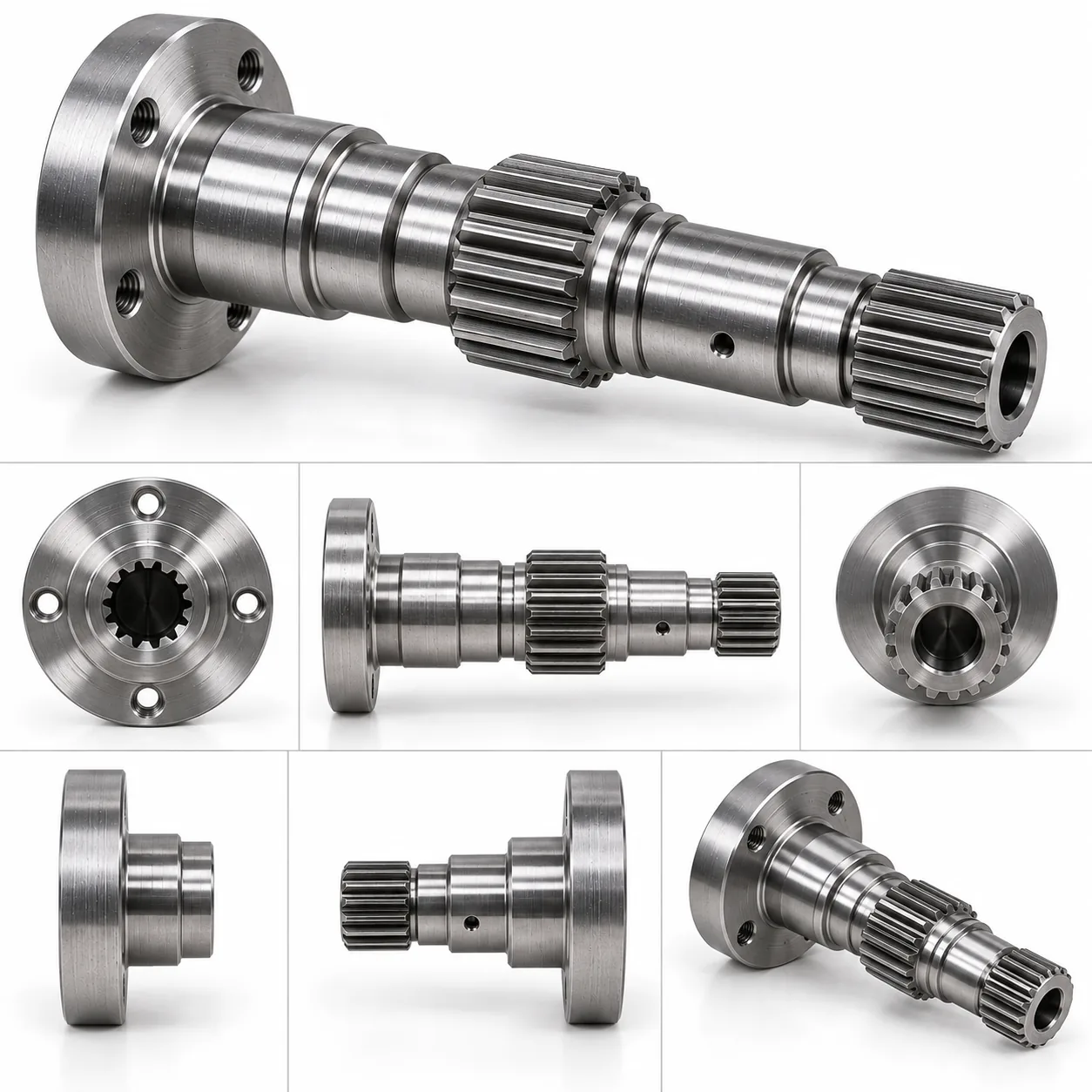
What "Complex" Means Once You Look at the Part
The part is a stepped shaft, 47.30 mm long, in aluminium 6061-T6. Four features sit on it, and each one wants a different setup:
| Feature | What it is | Why it gets its own setup |
|---|---|---|
| ① Six-lobe end | Rosette form, crest Ø8.90 and root Ø6.20, six lobes at 60.00°, 10.00 mm long | Milled, not turned. The R1.52 root arc caps the usable cutter at Ø3.0 |
| ② Fan lug | 97.50° sector on R15.00, standing 7.80 mm proud of the body, 10.20 mm long | Milled from solid; both flanks are radial planes through the axis |
| ③ Body | Cylinder Ø14.40 ±0.05, 13.10 mm long | Turned. It is datum A — every other feature is measured from its axis |
| ④ Square drive | 5.55 mm across flats, C1.6 × 45° on one corner only, 14.00 mm long | Milled and timed to the lug: the chamfered corner sits 45.00° from datum B |
The reason this is one supplier's job rather than two is the last column. All four features are referenced to the same axis, and two of them are timed to each other. Send the turning to one shop and the milling to another and every hand-off adds a re-fixture, and every re-fixture adds position error between features that were specified to stay concentric and clocked. On a 47.30 mm part there is not much length to absorb that.
The short answer to the UK question. Yes — but the test of a complex part is not how many operations it takes. It is whether the supplier can tell you what the part is when the file cannot. On this job the machining was routine and the file was not.
The Part Was Not the Hard Bit — the CAD File Was
The customer supplied a STEP file. It was measured twice, discretised independently at 0.8 mm and at 0.12 mm, and the two result sets cross-checked: all critical dimensions agreed to within 0.001 mm. That is not the same as the file being manufacturable. What the measurement found:
- It was not a solid. The model was an open shell of 1785 faces, every one of them planar. The Ø14.40 "cylinder" was a 24-sided polygon, inscribed R7.138 and circumscribed R7.200 — a 0.062 mm question nobody had answered.
- The six lobes were six different curves. They sat on a pitch of 55.00°, 55.75°, 61.75°, 66.50°, 63.00° and 58.00° instead of six equal 60.00° steps. Crest radii ran from R4.0915 to R4.7523, root radii from R2.8384 to R3.5306.
- The fan lug's outer edge was free-form. Its distance from the axis wandered continuously between R13.84 and R15.34. It was neither an arc about the axis nor a fittable eccentric arc — the best fit still left 0.64 mm of residual — so it could not be dimensioned as a radius or programmed as circular interpolation.
- Every shoulder was sharp. Zero fillet, zero chamfer, no relief grooves anywhere. Geometry a modeller can draw and a cutter cannot reach.
Taken together, that is a part which cannot be produced repeatably, cannot be gauged, and would not interchange from one piece to the next. Quoting it as drawn would have been the easy thing to do and the wrong thing to do.
What an Instant-Quote Portal Does With a File Like This
| What this job needed | Catalogue or instant-quote portal | EKINSUN |
|---|---|---|
| A six-lobe form whose lobes are six different curves on an uneven pitch | No catalogue part exists. Automatic quoting prices a bounding box or rejects the file | All six measured, then rebuilt on one common profile at 6 × 60.00°, crest Ø8.90 / root Ø6.20 |
| A Ø14.40 cylinder that is a 24-sided polygon in the file | Takes the polygon as the design intent and cuts flats, or fails to read the open shell at all | Asked which circle was meant; the circumscribed Ø14.400 was confirmed as nominal at ±0.05 and rebuilt as a true cylinder |
| A fan lug whose outer edge wanders between R13.84 and R15.34 | Cannot be programmed as circular interpolation; automatic CAM approximates it silently | Replaced with a true R15.00 arc about the axis — maximum departure 1.16 mm, agreed in writing before cutting |
| Shoulders modelled sharp, with no tool relief | Quotes it as drawn, then the cutter cannot reach the corner | C0.3 chamfers, R0.3 fillets and DIN 509-E relief added under a general note, moving no dimension |
| A 5.55 mm square drive with one corner chamfered and the other three left square | Not a standard drive size and not in any catalogue | Machined as measured, with the C1.6 × 45° on the 45.00° corner only — the part is handed, and the drawing says so |
Ten Questions, One Signature, Then Release
Nothing above was decided by us alone. Every difference between the supplied model and a manufacturable part was written into a clarification sheet: the measured value, the problem it causes, and the options — one to be ticked. Six items blocked production and had to be answered. Four were accepted as measured and only needed a confirmation. Eight further items — material, tolerance class, surface finish, datums, inspection — were set by EKINSUN and marked as needing no action.
The sheet came back signed on 14 August 2026. The released drawing was issued four days later, and it carries every customer-confirmed value in red, with everything derived by us in black. A machinist can see at a glance which numbers carry a signature and which do not.
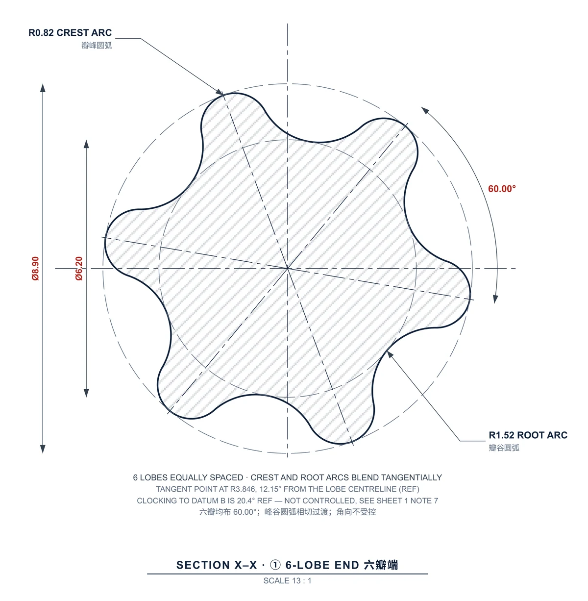
SECTION DETAIL · THE SIX-LOBE FORM REBUILT ON ONE COMMON PROFILE · RED = CUSTOMER-CONFIRMED, BLACK = DERIVED BY EKINSUN
The red-and-black split is not decoration. The crest Ø8.90 and root Ø6.20 are the customer's choice and cannot move without a new signature. The R0.82 crest arcs and R1.52 root arcs that connect them are ours — solved so that the two arcs meet tangentially and the form closes without a kink. If the customer ever changes Ø8.90, those two radii change with it, and the drawing shows whose number is whose.
The Four Decisions That Made It Manufacturable
| Feature | The supplied model | The released drawing | Max departure |
|---|---|---|---|
| ① Six-lobe end | Six different curves, pitch 55.00°–66.50° | Regular 6 × 60.00°, crest Ø8.90 / root Ø6.20 | 0.43 mm |
| ② Lug outer edge | Free-form curve, R13.84–15.34 about the axis | True R15.00 arc about datum A | 1.16 mm |
| ③ Cylinder | 24-sided polygon, inscribed R7.138 / circumscribed R7.200 | True cylinder Ø14.40 ±0.05 | 0.062 mm |
| Lengths | 10.000 / 10.201 / 13.099 / 14.000 = 47.300 overall | 10.00 / 10.20 / 13.10 / 14.00 = 47.30 overall | 0.001 mm |
// Four further rows — the lug flanks, the lug root undercut, the shoulders and the square drive — sit on the released drawing, which is not published here.
Read the right-hand column again: the largest change anywhere on the part is 1.16 mm, and the smallest is a thousandth of a millimetre. None of them was a liberty. Each one is a line the customer ticked, and each is listed on the drawing against the item number they ticked it on.
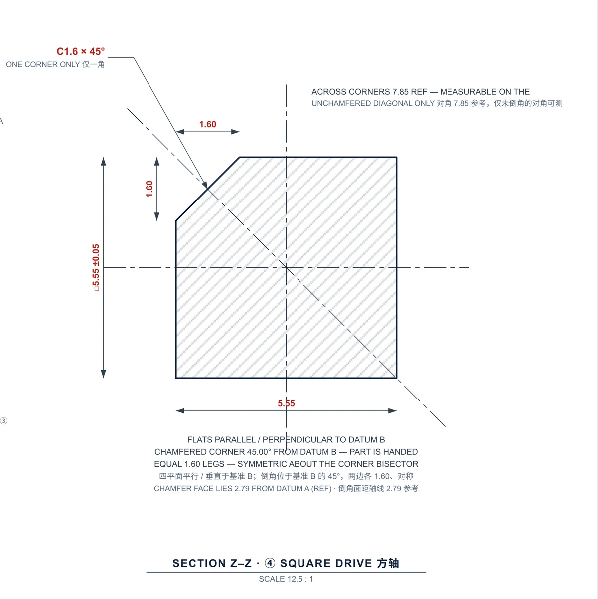
SECTION DETAIL · 5.55 MM SQUARE DRIVE · THE C1.6 CHAMFER DRAWN AS TWO EQUAL 1.60 LEGS SO NOBODY HAS TO ASSUME
One habit worth stealing from this sheet: where a single symbol stands in for two dimensions,
draw it out once. C1.6 × 45° means 1.60 mm measured along each of the two flats that meet
at that corner, so the chamfer is symmetric about the corner bisector. Everyone in the trade knows
that. It still gets asked, so both 1.60 legs are dimensioned and the chamfer face is given at 2.79 mm
from the axis for anyone checking it on a CMM.
Why 6061-T6, and What Else the Form Would Suit
6061-T6 was right here: the part is light-duty, the customer wanted it as-machined with no plating, and 6061 cuts the R1.52 root arcs cleanly with a Ø3.0 cutter. The same geometry works in other materials, with consequences worth knowing before you choose:
| Material | What changes on this part | When to pick it |
|---|---|---|
| Aluminium 6061-T6 | As machined here. Light, easy to cut, anodises if you want it later | General duty, low weight, lowest cost of the three |
| Aluminium 7075-T6 | Holds the 5.55 mm square better under torque; roughly twice the strength of 6061 | When the square drive is the loaded feature. Not weldable, and more expensive |
| Stainless 304 / 303 | Feeds and speeds drop sharply in the lobe roots; expect longer cycle time | Corrosive service or where the part must not be anodised. 303 if you want it to machine like 304 should |
| Titanium Gr.5 | Not a good match for this form — the Ø3.0 cutter in the root arcs is the limit | Honest answer: pick a different root radius first, or pick another material |
What a Part Like This Costs
There is no list price for this part, and putting one on the page would be a lie rather than a service. What can be published is the shape of the pricing and the things that move it.
| Quantity | How it prices |
|---|---|
| 1–5 pcs | Quote required. The engineering — measuring the file, the clarification sheet, the drawing — is a one-off cost carried by very few pieces, so it dominates the unit price |
| 10–50 pcs | Quote required. Setup and engineering are amortised; the unit price falls sharply against the 1–5 band and cycle time starts to dominate |
| 100+ pcs | Volume pricing. At this point the six-lobe form is the whole conversation — it is the cycle-time driver, and a small change to the root radius can change the tooling |
Why the price is different for every part
Eight things set the number. Generic lists of these are everywhere, so here is what each one did on this part:
| What drives the price | On this part |
|---|---|
| Material | Aluminium 6061-T6. Cheap to buy and easy to cut — but see the next row, because the material cost is decided by the stock size, not the finished weight (finished mass is 16.6 g) |
| Part dimensions | The R15.00 fan lug needs Ø30 bar even though the body is only Ø14.40. The largest feature buys the stock, and most of it becomes swarf |
| Tolerance | ISO 2768-m general, with ±0.05 on two features only. Putting ±0.05 on everything would add inspection time rather than machining time — a common and avoidable way to pay more |
| Geometry | The cost driver here. The R1.52 root arcs cap the usable cutter at Ø3.0, so the six-lobe form is cut with a small tool over many light passes |
| Machining time | Four features on one axis, and two of them timed to each other, so the setups have to hold the relationship rather than just the sizes |
| Surface finish | Ra 3.2 µm as-machined, no plating and no anodising. Asking for Ra 0.8 µm on the lobe flanks would change the finishing pass, not the roughing |
| Quantity | See the table above. On a part with this much engineering in front of it, the 1–5 band and the 100+ band are different businesses |
| Inspection | A first-article dimensional report covering every dimension on the drawing. That is real time on a CMM and it is priced, not free |
Why there is no price in this page's structured data. A made-to-order part with a signed clarification sheet in front of it is not a catalogue item, and a made-up price range would make the page look like one. The facts are published — material, sizes, tolerances, finish, inspection — and the number comes back within 12 hours once we have seen the file.
How the Job Ran
File received and measured twice
Discretised independently at 0.8 mm and 0.12 mm on the OpenCASCADE kernel, cross-checked: all critical dimensions agreed to within 0.001 mm. The rotation axis was established by least-squares fit on the plain cylindrical section.
Measurement drawing issued, marked not for manufacture
Every figure taken straight from the customer's file with nothing modified, so the customer could see what they had sent — including the per-lobe table showing all six lobes different.
Clarification sheet issued
Six blocking items, four accepted-as-measured items, eight items set by EKINSUN. Each blocking item carried the measured value, the problem, and the options to choose from — including "reproduce the model as-is", with its consequences spelled out.
Sheet returned signed
One option ticked on every blocking item. Our recommendation was taken on five of the six; on the lug symmetry the customer chose the tighter 97.50° rather than the rounder 90.00° we had offered.
Released for manufacture
Three sheets: views and the departure table, three sections and the decision record, plus dimensioned isometrics. Customer-confirmed values in red, EKINSUN-derived values in black, with a key on every sheet.
What This Case Generalises To
Three things travel from this job to any part that needs more than one process:
- Count the datums, not the operations. If features on your part have to stay concentric or clocked to each other, keep them under one supplier. The cost of splitting them is not the second setup fee, it is the stack of position error you cannot inspect out afterwards.
- Assume a scanned or exported file needs a decision, not a quote. Faceted solids, open shells and free-form curves where the designer meant an arc are the normal condition of reverse-engineered data, not an exception. Ask your supplier what they will do when they find one.
- Get the decisions on paper before the machine starts. A part with four features has four ways to be quietly wrong. Ten signed lines cost a week; a wrong batch costs the batch.
If you have a drawing, send the drawing. If you have a scan or a STEP file that came out of one, send it as it is — we will measure it and tell you what it does not say. If you have neither, a sketch on paper or the old part itself is enough to start; 3D scanning closes the gap and this page is what happens next. Drawings and files are covered by our NDA and confidentiality policy.
Frequently Asked Questions
Yes, and on a part like this one it is the only sensible way. The 6-lobe end, the fan lug, the Ø14.40 body and the 5.55 mm square drive all reference the same axis. Splitting them between a turning shop and a milling shop means re-fixturing between operations, and every re-fixture adds position error between features that have to stay concentric and timed to one another. EKINSUN runs all four features against one datum through qualified manufacturing partners.
Yes. A faceted export is normal input, not a problem. This job arrived as an open shell of 1785 planar faces in which the Ø14.40 cylinder was really a 24-sided polygon, inscribed R7.138 and circumscribed R7.200. What we do not do is guess which of those two numbers you meant. We measure the file, list every place where the model and a manufacturable nominal disagree, and ask you to choose before anything is cut.
It is a list of every question the CAD file cannot answer, with the measured value and the options set out against each one. On this job it ran to ten items: six that blocked production and four that were accepted as measured. You tick one option per item and sign. Nothing unconfirmed reaches the machine, and the released drawing then carries your choices in red so that no one downstream can change one quietly.
It matters more than almost anything else on the part. On this job the six lobes sat on an uneven pitch of 55.00°, 55.75°, 61.75°, 66.50°, 63.00° and 58.00° instead of six equal 60.00° steps, and the crest radii were spread across R4.0915 to R4.7523. A form like that cannot be produced repeatably, cannot be gauged, and no two pieces would interchange. It was rebuilt on a regular 6 × 60.00° pattern with one common lobe profile, crest Ø8.90 and root Ø6.20, and the largest departure from the supplied model was 0.43 mm.
One piece. The engineering work — measuring the file, writing the clarification sheet, issuing the drawing — is the same whether you order one or two hundred, so a single piece carries more of that cost per part, but EKINSUN takes single-piece orders and quotes them within 12 hours.
There is no list price, because no two of these parts are the same job. On this part the price is set by eight things: the material and the bar size the largest feature forces you to buy, the overall size, the tolerance, the geometry, the machining time, the surface finish, the quantity, and the inspection you want back with the parts. The geometry is usually the surprise — here the R1.52 root arcs cap the usable cutter at Ø3.0, so the six-lobe form is cut with a small tool over many passes and it drives the cycle time more than the other three features combined. Send the file or the drawing and EKINSUN returns a quote within 12 hours.
Related reading. Reverse engineering a broken drive shaft covers the case where there is no CAD at all; a stainless precision shaft with a keyway covers a single-axis part with tighter tolerances. Materials and their trade-offs are listed on materials we machine, and more finished work is in the portfolio. Parts in this family sit under precision shafts, gears and fittings. Deep-hole-drilled precision shafts cover the case where the bore, not the outside, decides the set-up.