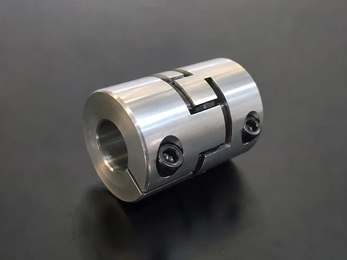
What We Machine — and Where the Catalogue Genuinely Stops
Every row below is a coupling we machine from a drawing. The middle column is there because the honest answer to “can’t I just buy this?” is sometimes yes, and an engineer spots a page that pretends otherwise — step bore couplings with a different bore at each end, for instance, are a normal stocked line. What a catalogue stocks is a matrix of bore pairs, and that matrix is short. Whether your pair is in it is the whole dividing line:
| What you need | In the catalogue? | At EKINSUN |
|---|---|---|
| A common pair — 10 mm to 3/8 in, 1/2 in to 12 mm — in steel, aluminium or 1.4305 / 303 | Stocked | Order it there. A stock coupling beats a machined one on price every time |
| Ø 25 H7 one end, 7/8 in the other, DIN 6885 key on one side and an imperial key on the other | Not in any matrix | Each end bored and keyed on its own, concentric in one setup |
| Outside diameter or length pinned by the housing around the coupling | Catalogue OD follows the bore — not selectable | Envelope is an input, not an output |
| 1.4404 / 316L, 42CrMo4, 17-4 PH or bronze | Mostly 1.4305 / 303, C45 and aluminium | Machined from the grade you specify, with EN 10204 3.1 on request |
| Spline bore — DIN 5480, involute or straight-sided | Not stocked in any rigid coupling range | Slotted, broached or wire EDM; measured from the mating shaft if no data survives |
| Bore matched to a shaft that is already worn undersize | Catalogue bores are nominal only | Shaft measured first, bore set to the fit you want on the real diameter |
| Quantity one, no tooling charge | Also fine — catalogues sell singles | Also fine. MOQ 1 is a normal order, and the drawing is kept for reorders |
Buy It Off the Shelf, or Have It Machined?
Rigid couplings are a deep, well-stocked catalogue category, so the honest first question is whether you need a machined one at all. This is the line we draw before quoting:
Buy off the shelf
A bore pair that exists in the matrix — 10 mm to 3/8 inch, 1/2 inch to 12 mm, 20 mm to 20 mm — in aluminium, ordinary steel or 1.4305 / 303, at the catalogue outside diameter and length. Local industrial supply stores stock these by the thousand. Buy it off the shelf: it will be on your bench tomorrow and cheaper in the catalogue than anything made to order — or contact us, we may have it in stock.
Have it machined — our lane
A bore pair that is not in any matrix, an outside diameter or length pinned by the housing around it, 1.4404 / 316L or 42CrMo4 instead of free-machining stainless, a spline bore, a keyway that has to match a worn original, or a coupling half for a machine whose maker is gone. Here the part is not a size choice, it is a drawing.
Not sure which side you are on? Send the two shaft diameters, the torque and whether anything constrains the outside diameter. If a catalogue coupling fits, we will name it and tell you to order it — we only want the jobs that need machining.
The Line Catalogues Never Print: H7 Before Clamping
This is the detail that decides whether a machined clamp coupling fits, and it appears on almost no product page anywhere. A one-piece clamp coupling is slit down its length. Tightening the clamp screws springs that slit closed, which pulls the bore in on the shaft. So the bore has two different sizes and two different shapes depending on when you measure it:
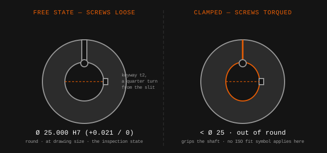
| State | What the bore is | Why it matters |
|---|---|---|
| Free state (screws loose) | Round, at drawing size — e.g. Ø 25.000 H7, +0.021 / 0 | This is the inspection state. It is the only condition in which an H7 number is checkable with a plug gauge or a bore gauge |
| Clamped state (screws torqued) | Undersize and slightly oval — the slit has closed by a few hundredths | This is the working state, and it is what grips the shaft. It is not a state you can put an ISO fit symbol on |
Two consequences follow, and both are machining instructions rather than opinions:
- The slit is the last cut. Parting the slit releases residual stress in the bar and the bore moves by a few microns. Cut it before finishing the bore and the finished size is a guess.
- The bore is inspected after the slit, in the free state. Inspecting before the slit measures a part that no longer exists.
What to write on your drawing: put the fit and the state together — Ø 25.000 H7 BEFORE CLAMPING. Without the state, two shops will measure two different numbers and both will be able to argue they were right.
Keyway Depth on a Coupling Is t2, Not t1
DIN 6885-1 gives two depths for every key size: t1 is cut into the shaft, t2 into the hub — which on a coupling means the bore. Copying t1 into the coupling is the most common keyway error on drawings that reach us; it leaves the key standing proud and the coupling will not seat. The hub column below is the one you want:
| Shaft diameter | Key b × h | Shaft depth t1 | Hub / coupling depth t2 |
|---|---|---|---|
| over 8 to 10 mm | 3 × 3 | 1.8 mm | 1.4 mm |
| over 10 to 12 mm | 4 × 4 | 2.5 mm | 1.8 mm |
| over 12 to 17 mm | 5 × 5 | 3.0 mm | 2.3 mm |
| over 17 to 22 mm | 6 × 6 | 3.5 mm | 2.8 mm |
| over 22 to 30 mm | 8 × 7 | 4.0 mm | 3.3 mm |
| over 30 to 38 mm | 10 × 8 | 5.0 mm | 3.3 mm |
| over 38 to 44 mm | 12 × 8 | 5.0 mm | 3.3 mm |
| over 44 to 50 mm | 14 × 9 | 5.5 mm | 3.8 mm |
| over 50 to 58 mm | 16 × 10 | 6.0 mm | 4.3 mm |
| over 58 to 65 mm | 18 × 11 | 7.0 mm | 4.4 mm |
| over 65 to 75 mm | 20 × 12 | 7.5 mm | 4.9 mm |
Width tolerance follows the fit class, not the size: JS9 in the hub for a normal fit (N9 in the shaft), D10 for a free fit (H9 shaft), P9 both for a press fit. Key height is h9 and key length h14. Values above are the DIN 6885-1 parallel-key series; imperial keys to BS 4235 or ANSI B17.1 are cut the same way from the corresponding table.
On a clamp coupling, the keyway sits a quarter turn from the slit. Put the keyway next to the slit and you have removed material from the exact place the clamp needs to hinge — the section left between keyway and slit is what carries the clamping load. Key and clamp then work together: the key takes the torque, the clamp takes the axial position.
Rigid Coupling Forms — and Where Each One Ends
| Form | How it drives | Where it ends |
|---|---|---|
| One-piece clamp | Slit body, clamp screws spring the bore shut on the shaft | Needs a free shaft end to slide onto — you cannot fit it between two mounted machines |
| Two-piece clamp | Two half-shells drawn together around both shafts | Installs without moving either machine; slightly lower torque per size than one-piece |
| Set-screw sleeve | Grub screws bear on the shaft flats | Marks the shaft, and creeps under reversing load or vibration |
| Keyed sleeve | Key in a DIN 6885 keyway carries the torque | Highest torque, but backlash equal to the keyway clearance unless clamped as well |
| Flanged (bolted halves) | Two hubs bolted face to face on a bolt circle | High torque and easy disassembly, but the longest and heaviest form |
| Step bore | A different bore diameter at each end | Only as good as the bore pair available — see the next section |
Every form in that table tolerates exactly zero misalignment. That is what rigid means. If your two shafts are not already held in line by the housing, a rigid coupling will drive the error straight into the bearings on both sides and the bearings will fail first. In that case you want a jaw, bellows, beam or Oldham coupling — all of them catalogue parts, none of them worth machining.
Materials — and the All-Stainless Galling Problem
Catalogue rigid couplings are mostly 1.4305 / 303 because it machines fast and the sulphur that makes it free-cutting is invisible in a stock listing. It is also the grade you should not use in washdown, marine or medical service. When a coupling is specified in 1.4404 / 316L, a second problem arrives with it:
Stainless clamp screws in a stainless body gall. Austenitic stainless sliding on austenitic stainless has almost no oxide film between the threads, so A4-80 screws in a 316L coupling can cold-weld on first tightening — and then shear instead of coming out. On an all-316L coupling we either supply anti-seize on the threads or specify a screw grade that is not the same material as the body. Catalogue couplings sidestep this by not being 316L in the first place.
| Material | Why you would pick it | What it costs you |
|---|---|---|
| 1.4305 / 303 | The catalogue default; fastest to machine, lowest price | Poor corrosion resistance; not for washdown, marine or medical |
| 1.4301 / 304 | General corrosion resistance at moderate cost | Gummier to cut than 303; still attacked by chlorides |
| 1.4404 / 316L | Chloride and washdown service; the usual medical and marine choice | Slowest to machine, highest stainless price, and the galling problem above |
| C45 | Cheap, strong, weldable — the default when corrosion is not in play | Rusts bare; needs plating, oxide or paint |
| 42CrMo4 | The torque grade — quenched and tempered for the highest loads per size | Costlier, and heat treatment has to be sequenced around the bore |
| 6061 | Lowest rotating inertia; the choice on fast or portable drives | Soft bore — clamp marks and thread pull-out under repeated assembly |
| 7075 | Aluminium strength where 6061 yields at the clamp | Much worse corrosion resistance than 6061; not weldable |
The Jobs That Land on Our Bench
"Can you supply? Only need one."
That sentence opens most coupling jobs we take, and the answer is that quantity one is a normal order rather than a surcharge case. A finished drawing goes straight to a fixed price. There is no tooling to amortise on a turned part, and the drawing is kept, so a repeat next year is quicker and cheaper than the first.
"The new gearmotor is metric, the machine shaft is imperial, and nothing in the catalogue pairs them."
The most common one-off coupling job there is. Each end is bored for its own shaft and keyed to its own standard — DIN 6885 one side, an imperial key the other — with both bores turned concentric in a single setup so the joined shafts still run true.
"The coupling half is splined and the maker no longer exists."
Splined coupling halves are the one bore style with no catalogue equivalent at all. Send the mating shaft with the broken half; the spline is measured from the parts themselves and cut by slotting, broaching or wire EDM, and we make a spare in the same run so the machine is not waiting next time.
Matched running gear: couplings rarely arrive alone. We machine the mating shaft, shaft collars, bushings and machine keys in the same material and the same run, so the assembly arrives as one certified set. For the type decision — rigid against flexible — start at custom shaft couplings. If the original is broken or unmarked, see copying a part from a sample.
Will it fit? Two shafts, two bores, one coupling
A 25 mm gearbox shaft and a 7/8″ motor shaft (22.225 mm) never share a bore: the coupling is bored 25 H7 at one end and 22.225 H7 at the other, concentric in one setup. The keyways follow the shafts as well — DIN 6885 puts an 8 × 7 key on a 25 mm shaft with the hub-side depth t2 at 3.3 mm, while a 7/8″ shaft carries a 3/16″ or 1/4″ inch key. Send both shaft diameters from a micrometer and both key sizes; if either shaft is worn under the old hub, say so and we bore to the measured size.
What do I need to couple a 25 mm gearbox shaft to a 7/8″ motor shaft?
A rigid coupling with a 25 H7 keyed bore at one end and a 7/8″ H7 keyed or clamp bore at the other, an outside diameter that clears the guard, and shafts that are actually in line — a rigid coupling corrects nothing, so if the two are offset the same two bores go into a flexible coupling instead.
Same coupling, but a spline bore, 316L, or longer
A DIN 5480 spline at one end, 316L for a washdown drive, a longer body for a wider gap, a clamp slot instead of set screws, or a bore pair no matrix prints — each is a variant of the same drawing, one piece and up, quoted in 12 hours.
Frequently Asked Questions
It names the state the bore is inspected in. A one-piece clamp coupling is slit down its length, so tightening the clamp screws springs the bore closed onto the shaft — once clamped it is smaller than nominal and no longer round. A bore called Ø 25.000 H7 (+0.021 / 0) therefore only means something with the screws loose, in the free state. It also fixes the machining order: cutting the slit releases stress and moves the bore by a few microns, so the slit is the last cut and the bore is measured after it, not before. If your drawing does not say which state applies, two shops will measure two different numbers and both will believe they are right.
t2 — the hub depth. DIN 6885-1 gives two depths for every key size: t1 is cut into the shaft, t2 into the hub or coupling. For a 25 mm shaft the key is 8 × 7 mm, t1 is 4.0 mm in the shaft and t2 is 3.3 mm in the coupling bore. Copying t1 into the coupling is the single most common keyway mistake we see on incoming drawings; it leaves the key proud and the coupling will not seat. Width tolerance follows the fit class: JS9 in the hub for a normal fit, D10 for a free fit, P9 for a press fit.
Yes, and catalogue makers stock these too — a step bore coupling is a normal shelf item at industrial supply stores. What a catalogue stocks is a fixed matrix of bore pairs. If your pair is in the matrix, buy it. If your pair is Ø 25 H7 one end and 7/8 inch the other, with a DIN 6885 keyway on one side and an imperial key on the other, that combination is not in anybody's matrix and it becomes a drawing part — a five-minute change on a drawing and impossible on a shelf.
Galling. Austenitic stainless slides against austenitic stainless with almost no oxide film between the threads, so A4-80 screws in a 1.4404 / 316L body can cold-weld solid on first tightening — the screw then shears instead of coming out. It is a real risk on any all-stainless clamp coupling, and catalogue couplings avoid it by being made in 1.4305 / 303 with alloy-steel screws. Where the whole part must be 316L we supply anti-seize on the threads, or specify a different screw grade so the two mating materials are not identical.
Yes. Internal splines — DIN 5480, involute or straight-sided — are cut by slotting, broaching or wire EDM. This is the usual route when a splined coupling half from an old gearbox is no longer available, because splined couplings are the one bore style catalogues do not stock. If no spline data survives, send the mating shaft and the spline is measured from the part itself.
No. A rigid coupling transmits every bit of misalignment straight into the bearings on both sides, and the bearings fail long before the coupling does. Rigid is correct only where the two shafts are already aligned by the housing, or where you want them locked together as one shaft. If there is angular, parallel or axial misalignment, you want a jaw, bellows, beam or Oldham coupling — those are catalogue parts and you should buy them off the shelf rather than have anything machined.
One piece. Send the two shaft diameters and the fit you want, the keyway or clamp arrangement, the maximum outside diameter and length if a housing constrains them, and the material. A finished drawing goes straight to a fixed-price quote; a dimensioned sketch or the worn original works just as well — we redraw it into an approval PDF and machine only after you sign it off. Quote in 12 hours.
Get a Rigid Coupling Quoted
Two shaft diameters, keyway or clamp, and any envelope limit — or the worn original. Engineers reply in 12h.
// Qty & price
1 pc
Sample price
Confirm fit before a run
10–50
Unit price drops
Setup cost shared
100+
Best price
All tiers quoted upfront
- →No distributor — you pay the maker directly
- →CAD saved after first order — reorder anytime at lower unit price