This chart is here because we cut these grooves ourselves: EKINSUN turns threaded parts to drawing with the undercut the drawing specifies — from one piece. The sizes below are the part anyone can look up. The part that reaches us is the undercut that has to run out against a shoulder DIN 76-1 never anticipated, or a groove that must match a mating part already in service. See custom bolts machined to drawing.
This page exists because the undercut cost us money. One of our own drawings for a thread adapter, M15×1 female to M16×1.5 male, carried an undercut of 0.3 mm. It is not machinable at that width, and it would not have worked if it were. The numbers below are the part anyone can look up. The part that matters on the shop floor is under Too narrow, too wide, missing and A real case.
What a thread undercut is — and what it is not
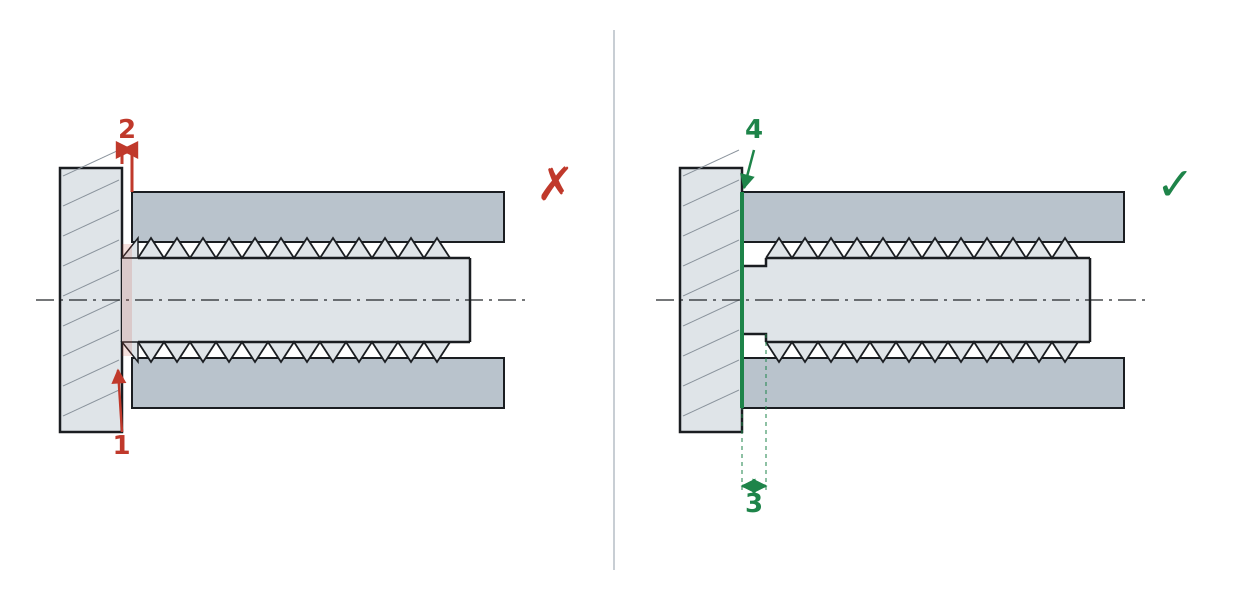
A thread undercut (also called a thread relief or relief groove) is a groove turned in at the end of the thread. Its diameter sits below the thread root, so the thread stops in a clean groove instead of tapering away into the shoulder.
What it is not is the thread run-out. The run-out happens on its own: the tool cannot drop to full depth or leave it instantly, so the thread profile fades away over one or two turns. The run-out is a taper carrying partial, undersized threads — and it is exactly what the mating part lands on. The undercut removes it.
The difference in one line: the run-out is the problem, the undercut is the fix. A drawing note saying "thread run-out per ISO 4755" has ordered something different from "thread undercut per ISO 4755".
What people actually call it
Almost no enquiry uses the words "thread undercut". People describe the place instead of naming the feature, and most of the time it is still clear what they mean. The usual descriptions:
| What people say | What they mean | Is that right? |
|---|---|---|
| "the groove at the end of the thread" | Thread undercut | Yes, exactly that |
| "the smooth bit before the shoulder" | Thread undercut | Yes — smooth and stepped down in diameter |
| "the neck" | Thread undercut | Yes, common shop usage |
| "the relief" | Thread undercut | Yes — thread relief is the formal alternative name |
| "where the thread runs out" | Thread run-out | No — that is the area without an undercut |
| "the step where the thread stops" | Usually the run-out taper | No — the taper is not a groove |
| "undercut" with no qualifier | May be a shaft undercut per DIN 509 | Partly — DIN 509 sits at a shaft shoulder, not at a thread |
In German the same feature is a Gewindefreistich and the run-out is the Gewindeauslauf; in French, gorge de dégagement and sortie de filet; in Norwegian, frispor and gjengeutløp.
Need a shaft or bolt with a thread undercut to DIN 76? EKINSUN is a custom parts manufacturer: we make shafts, bolts and threaded parts with the undercut on your drawing to your drawing, sketch or sample — steel, 42CrMo4, 304 or 316L stainless steel or brass — from 1 piece, quoted in 12 hours and shipped duties paid. Already a catalogue size? Ask us too — we may have it in stock, and larger quantities cost less per piece. How ordering without CAD works →
What the undercut is for
It has two jobs, and the second is the one that catches people out:
- Room for the tool. When single-point turning a thread, the threading insert has to come out at the end of the pass without running into the shoulder. With no undercut there is no clean exit point — the last turn comes out incomplete, or the tool crashes.
- Room for the mating part. This is the one that decides whether the joint works. The nut or fitting going on has its own lead-in chamfer, but its first load-bearing turn sits well forward. When that turn meets the tapered run-out, the part stops there. You feel resistance and read it as tight — but the face was never reached.
Sizes by pitch
ISO 4755:1983 covers thread undercuts for external metric ISO threads. DIN 76-1 additionally splits them into four forms: A and B for external threads, C and D for internal threads. A and B share the same geometry and differ only in length, as do C and D. A and C are the normal case; the short forms B and D exist for situations where the normal width will not fit.
Everything is sized from the pitch P, not the nominal diameter. An M20×1.5 gets the same undercut width as an M10×1.5 — only the undercut diameter follows the nominal size.
| Pitch P | Width g2 = 3.5 × P | Practical floor ≈ 3 × P | Radius r = 0.5 × P | Undercut Ø dg = d − 1.6 × P |
|---|---|---|---|---|
| 0.5 | 1.75 | 1.5 | 0.25 | d − 0.8 |
| 0.7 | 2.45 | 2.1 | 0.35 | d − 1.12 |
| 0.8 | 2.8 | 2.4 | 0.4 | d − 1.28 |
| 1.0 | 3.5 | 3.0 | 0.5 | d − 1.6 |
| 1.25 | 4.375 | 3.75 | 0.625 | d − 2.0 |
| 1.5 | 5.25 | 4.5 | 0.75 | d − 2.4 |
| 1.75 | 6.125 | 5.25 | 0.875 | d − 2.8 |
| 2.0 | 7.0 | 6.0 | 1.0 | d − 3.2 |
| 2.5 | 8.75 | 7.5 | 1.25 | d − 4.0 |
| 3.0 | 10.5 | 9.0 | 1.5 | d − 4.8 |
These values are computed from the DIN 76-1 sizing formulas, not transcribed from the dimensional table. For a drawing, use the current edition of the standard — the tabulated limits there govern. For deciding whether the undercut fits at all, the formulas are enough.
The common threads worked out
An M4 with a 0.7 mm pitch takes a 2.45 mm wide undercut at Ø2.88 — the same formulas with the numbers filled in. Coarse threads first, then the fine pitches, where the smaller pitch gives a noticeably narrower undercut.
| Thread | Pitch P | Width g2 | Floor ≈ 3 × P | Undercut Ø dg |
|---|---|---|---|---|
| M4 | 0.7 | 2.45 | 2.1 | 2.88 |
| M5 | 0.8 | 2.8 | 2.4 | 3.72 |
| M6 | 1.0 | 3.5 | 3.0 | 4.4 |
| M8 | 1.25 | 4.375 | 3.75 | 6.0 |
| M10 | 1.5 | 5.25 | 4.5 | 7.6 |
| M12 | 1.75 | 6.125 | 5.25 | 9.2 |
| M16 | 2.0 | 7.0 | 6.0 | 12.8 |
| M20 | 2.5 | 8.75 | 7.5 | 16.0 |
| M24 | 3.0 | 10.5 | 9.0 | 19.2 |
| M10×1.25 | 1.25 | 4.375 | 3.75 | 8.0 |
| M12×1.25 | 1.25 | 4.375 | 3.75 | 10.0 |
| M16×1.5 | 1.5 | 5.25 | 4.5 | 13.6 |
| M20×1.5 | 1.5 | 5.25 | 4.5 | 17.6 |
Too narrow, too wide, missing — what each one does
No undercut at all
The thread tapers away. The nut going on lands its first load-bearing turn on that taper and stops before it touches the face. What follows, in order: the sealing face never bears, so the joint leaks or works loose; anyone who tightens further puts the torque into the run-out instead of into preload; the leading turns get crushed or stripped. On a fitting with a sealing edge the part is scrap after that.
Undercut too narrow
Functionally the same as having none, as long as the groove is narrower than the run-out it is meant to remove. Then there is the manufacturing side: below roughly 1 mm there is no grooving tool that will cut it cleanly at depth. A 0.3 mm wide parting blade breaks before it is 1.2 mm deep. A 0.3 mm callout does not describe a groove, it describes a scratch — and the shop either flags it, if they are paying attention, or quietly does something else if they are not.
Undercut too wide
The error in the other direction is underrated. Three effects:
- You lose usable thread. On short adapters and studs, length is the scarce resource. Every millimetre of undercut comes off the load-bearing thread — and capacity depends on how many turns are actually engaged.
- The section is weakened. The undercut root sits below the thread root: on an M12 with dg = 9.2 mm, the load-bearing section there is smaller than in the thread itself. Under tension the part fails at the groove, not in the thread.
- The undercut root is a notch. Under cyclic load the fatigue crack starts exactly there. That is why the standard specifies a radius r = 0.5 × P — it is not cosmetic, it lowers the stress concentration. A sharp-cornered undercut is a designed-in break point.
The working rule: as wide as it needs to be for the mating part to seat, and not a millimetre wider. The standard value is g2 = 3.5 × P. If the part is too short for that, drop to the short form B, and below that to whatever still does the job. Leaving it out entirely is the one option that reliably does not work.
A real case: 0.3 mm on the drawing
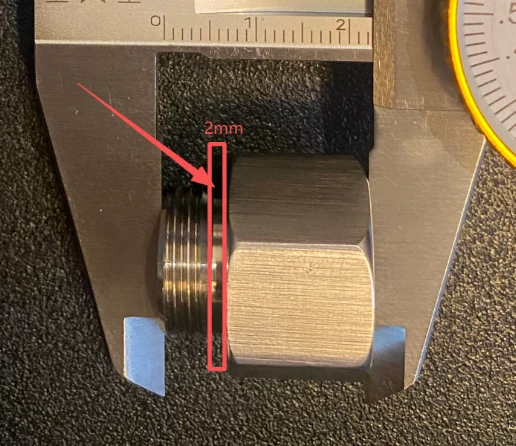
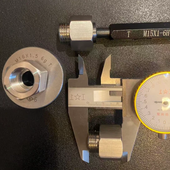
A thread adapter: M15×1 female, M16×1.5 male, 10 mm through bore, 22.5 mm overall length, 22 mm across flats. The drawing called out a 0.3 mm undercut between the hex and the threaded spigot. By the standard, at P = 1.5, it should have been about 5.25 mm, with a practical floor of 4.5 mm.
At 22.5 mm overall you cannot fit 5.25 mm of undercut — the whole threaded spigot is only 7.5 mm long. That is precisely why the number ended up so small: the intent was to keep as much thread as possible. The flaw in that reasoning is that thread the mating part can never reach carries nothing.
The machinist's report was that 0.3 mm is not producible, and that the joint only works from about 2 mm. That sits below the standard value and below the 3 × P rule of thumb — it is the compromise a short part forces. It works because it does the one job that matters here: the mating part reaches the face. It costs 1.7 mm of usable thread to do it, and the customer should hear that before the parts are cut, not after.
This is how these come in:
- "The fitting will not go all the way down, there is a two tenths gap left — is that the thread?"
- "We need the adapter shorter but the thread has to stay the same length. Can you do that?"
- "The old drawing has no undercut on it at all, and the part has been in service for twenty years."
- "The stud snapped at the groove, always in the same place."
That last one is nearly always the radius: cut sharp instead of r = 0.5 × P. For a rebuild the broken part is enough to work from — see reverse engineering from a sample.
When you do not need a machine shop for this
The comparison below is against ordinary catalogue stock — set screws, studs, spigot bolts and adapters from a stockist's range.
| What is needed | Catalogue stock | At EKINSUN |
|---|---|---|
| Standard part with a standard undercut, standard length | stocked, off the shelf | Buy it there, or ask us — standard sizes may be in stock with us, and the more pieces, the lower the unit price; for one piece today, a local stockist is faster. |
| Undercut narrower than standard because the length will not allow it | Not offered — catalogue parts follow the standard or have no undercut at all | Width to your call, with the lost thread length stated up front |
| Two different threads on one part with a shoulder between them | Adapters exist only in common pairings | Any pairing, undercut sized for both ends |
| Rebuild of a snapped part with no drawing | Not possible — there is no part number to order | Send the sample, we measure it and size the undercut properly |
| Material 304 or brass in a standard size | Held in stock | No advantage on our side — material alone is not a reason to have something made |
| Undercut with a specified root radius for fatigue life | Not specifiable | Radius to drawing, with an inspection report on request |
Materials and how they get cut
Undercuts get turned in the same operation as the thread, on a sliding-head lathe or a CNC turning centre. Common materials are 1.4305 (X8CrNiS18-9, AISI 303) as the free-machining stainless for turned parts, 1.4301 (X5CrNi18-10, AISI 304) and 1.4404 (X2CrNiMo17-12-2, AISI 316L) where corrosion matters, brass CuZn39Pb3 for fittings, and aluminium 6061 and 7075. Quenched and tempered 42CrMo4 (1.7225) goes in where the undercut root has to survive cyclic load.
EKINSUN is a manufacturer of turned and milled parts to drawing, MOQ 1, quote in 12 hours. If your drawing has no undercut on it, we ask before we cut — which is exactly what would have prevented the case above. Related: CNC turning, adapters and fittings, non-standard thread bolts. Related tables: metric bolt torque chart, dowel pin size chart.
The other groove on a turned shaft is the circlip groove; its diameter, width and edge margin by shaft size are in the circlip groove size chart.
Common questions about thread undercuts
The standard width is g2 = 3.5 × P, and as a rule of thumb an undercut should be at least 3 × P wide. For M16×1.5 with P = 1.5 that is 5.25 mm and 4.5 mm respectively. If the part is too short for that, drop to the short form B. Below roughly 1 mm the groove can no longer be cut cleanly, and below the run-out length it stops doing its job.
The run-out happens on its own: the tool cannot reach full depth instantly, so the thread profile fades over one or two turns into a taper. That taper is what the mating part lands on. The undercut is a groove deliberately turned in below the thread root that removes the taper. The run-out is the problem, the undercut is the fix.
The mating part lands its first load-bearing turn on the tapered run-out and stops before it reaches the shoulder. You feel resistance and read the joint as tight, but it is not clamped. The sealing face never bears, tightening torque goes into the run-out instead of into preload, and the leading thread turns get crushed or stripped when someone pulls harder.
Yes, and it is the underrated failure. A wide undercut eats usable thread length, which lowers capacity on short adapters and studs. It also cuts the section below the thread root: on M12 with dg = 9.2 mm the part is thinner at the groove than in the thread, so it fails there under tension. Under cyclic load the fatigue crack starts at the undercut root, which is why the standard specifies the radius r = 0.5 × P.
Forms A and B are for external threads, forms C and D for internal threads. A and B share the same geometry and differ only in length, and so do C and D. A and C are the normal case. Use the short forms B and D only when the normal width will not fit, which typically means short spigots and adapters.
For external threads dg = d − 1.6 × P. On M12 with P = 1.75 that gives 9.2 mm, on M16×1.5 it is 13.6 mm, and on M20 with P = 2.5 it is 16.0 mm. The diameter sits below the thread root, otherwise the undercut would not clear the thread profile completely.
Not necessarily as a dimension, but it should be called out. A note such as thread undercut per ISO 4755 is enough and is safer than guessing a number. If nothing is stated the shop decides, and the run-out becomes whatever the tooling happened to leave. If the sample broke at the groove we check the radius as well, because that is where fatigue cracks start.
Need a part with an undercut?
Turned parts, thread adapters and special fasteners to your drawing — MOQ 1, quote in 12 hours. If the undercut is missing or will not fit, we say so before cutting. Send a drawing, a sketch or a sample.