EKINSUN turns shafts, pins, spacers and bushings with the circlip groove cut in the same setup, from 1 piece. The two tables below give the groove for every DIN 471 shaft ring from 3 to 100 mm and every DIN 472 bore ring from 8 to 100 mm — the sizes a drawing needs and the sizes a worn part is checked against.
What groove does a 25 mm shaft need? Ø23.9 mm, 1.3 mm wide (H13, 0 / +0.14 mm) and 0.55 mm deep, for a ring 1.2 mm thick, with at least 1.7 mm of shaft beyond the groove. A 25 mm bore takes a groove Ø26.2 × 1.3 mm.
DIN 471 external circlip grooves — shafts 3 to 100 mm
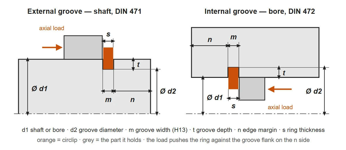
A DIN 471 ring sits in a groove smaller than the shaft: on a 10 mm shaft the groove is Ø9.6 mm and 0.2 mm deep, on a 50 mm shaft Ø47 mm and 1.5 mm deep. The row is chosen by the shaft diameter, and the ring follows from it. Groove width m is the ring thickness s plus 0.1 mm up to the 1.75 mm ring, plus 0.15 mm from the 2 mm ring up. External circlips are also called snap rings or retaining rings; the groove is the same.
| Shaft d1 | Ring thickness s | Groove Ø d2 | Groove width m (H13) | Groove depth t | Edge margin n min. |
|---|---|---|---|---|---|
| 3 mm | 0.4 | 2.8 | 0.5 | 0.1 | 0.3 |
| 4 mm | 0.4 | 3.8 | 0.5 | 0.1 | 0.3 |
| 5 mm | 0.6 | 4.8 | 0.7 | 0.1 | 0.3 |
| 6 mm | 0.7 | 5.7 | 0.8 | 0.15 | 0.5 |
| 7 mm | 0.8 | 6.7 | 0.9 | 0.15 | 0.5 |
| 8 mm | 0.8 | 7.6 | 0.9 | 0.2 | 0.6 |
| 9 mm | 1 | 8.6 | 1.1 | 0.2 | 0.6 |
| 10 mm | 1 | 9.6 | 1.1 | 0.2 | 0.6 |
| 11 mm | 1 | 10.5 | 1.1 | 0.25 | 0.8 |
| 12 mm | 1 | 11.5 | 1.1 | 0.25 | 0.8 |
| 13 mm | 1 | 12.4 | 1.1 | 0.3 | 0.9 |
| 14 mm | 1 | 13.4 | 1.1 | 0.3 | 0.9 |
| 15 mm | 1 | 14.3 | 1.1 | 0.35 | 1.1 |
| 16 mm | 1 | 15.2 | 1.1 | 0.4 | 1.2 |
| 17 mm | 1 | 16.2 | 1.1 | 0.4 | 1.2 |
| 18 mm | 1.2 | 17 | 1.3 | 0.5 | 1.5 |
| 19 mm | 1.2 | 18 | 1.3 | 0.5 | 1.5 |
| 20 mm | 1.2 | 19 | 1.3 | 0.5 | 1.5 |
| 21 mm | 1.2 | 20 | 1.3 | 0.5 | 1.5 |
| 22 mm | 1.2 | 21 | 1.3 | 0.5 | 1.5 |
| 24 mm | 1.2 | 22.9 | 1.3 | 0.55 | 1.7 |
| 25 mm | 1.2 | 23.9 | 1.3 | 0.55 | 1.7 |
| 26 mm | 1.2 | 24.9 | 1.3 | 0.55 | 1.7 |
| 28 mm | 1.5 | 26.6 | 1.6 | 0.7 | 2.1 |
| 29 mm | 1.5 | 27.6 | 1.6 | 0.7 | 2.1 |
| 30 mm | 1.5 | 28.6 | 1.6 | 0.7 | 2.1 |
| 32 mm | 1.5 | 30.3 | 1.6 | 0.85 | 2.6 |
| 34 mm | 1.5 | 32.3 | 1.6 | 0.85 | 2.6 |
| 35 mm | 1.5 | 33 | 1.6 | 1 | 3 |
| 36 mm | 1.75 | 34 | 1.85 | 1 | 3 |
| 38 mm | 1.75 | 36 | 1.85 | 1 | 3 |
| 40 mm | 1.75 | 37.5 | 1.85 | 1.25 | 3.8 |
| 42 mm | 1.75 | 39.5 | 1.85 | 1.25 | 3.8 |
| 45 mm | 1.75 | 42.5 | 1.85 | 1.25 | 3.8 |
| 48 mm | 1.75 | 45.5 | 1.85 | 1.25 | 3.8 |
| 50 mm | 2 | 47 | 2.15 | 1.5 | 4.5 |
| 52 mm | 2 | 49 | 2.15 | 1.5 | 4.5 |
| 55 mm | 2 | 52 | 2.15 | 1.5 | 4.5 |
| 56 mm | 2 | 53 | 2.15 | 1.5 | 4.5 |
| 58 mm | 2 | 55 | 2.15 | 1.5 | 4.5 |
| 60 mm | 2 | 57 | 2.15 | 1.5 | 4.5 |
| 62 mm | 2 | 59 | 2.15 | 1.5 | 4.5 |
| 63 mm | 2 | 60 | 2.15 | 1.5 | 4.5 |
| 65 mm | 2.5 | 62 | 2.65 | 1.5 | 4.5 |
| 68 mm | 2.5 | 65 | 2.65 | 1.5 | 4.5 |
| 70 mm | 2.5 | 67 | 2.65 | 1.5 | 4.5 |
| 72 mm | 2.5 | 69 | 2.65 | 1.5 | 4.5 |
| 75 mm | 2.5 | 72 | 2.65 | 1.5 | 4.5 |
| 78 mm | 2.5 | 75 | 2.65 | 1.5 | 4.5 |
| 80 mm | 2.5 | 76.5 | 2.65 | 1.75 | 5.3 |
| 82 mm | 2.5 | 78.5 | 2.65 | 1.75 | 5.3 |
| 85 mm | 3 | 81.5 | 3.15 | 1.75 | 5.3 |
| 88 mm | 3 | 84.5 | 3.15 | 1.75 | 5.3 |
| 90 mm | 3 | 86.5 | 3.15 | 1.75 | 5.3 |
| 92 mm | 3 | 88.5 | 3.15 | 1.75 | 5.3 |
| 95 mm | 3 | 91.5 | 3.15 | 1.75 | 5.3 |
| 100 mm | 3 | 96.5 | 3.15 | 1.75 | 5.3 |
Values follow the DIN 471 table for the regular series; check the edition your drawing calls for. Groove depth t = (d1 − d2) / 2, worked out from the table. Intermediate shaft sizes that some ring makers list (23, 27 or 33 mm, for example) are left out — ask for the row and it comes with the quote.
Need the shaft with the groove already in it? We turn shafts, pins and axles with DIN 471 grooves in 303 (1.4305), 304 (1.4301), 316L (1.4404), 6061 and 7075 aluminium, brass and alloy steel, from 1 piece; the more pieces, the lower the unit price. Standard ring sizes can also be supplied from stock. Quote within 12 hours.
DIN 472 internal circlip grooves — bores 8 to 100 mm
A DIN 472 ring sits in a groove larger than the bore: a 20 mm bore gets a Ø21 mm groove, the 47 mm housing bore of a 6204 bearing a Ø49.5 mm groove 1.85 mm wide. For a bore, the edge margin n runs from the groove to the face where the bore opens — the side the ring is pushed toward.
| Bore d1 | Ring thickness s | Groove Ø d2 | Groove width m (H13) | Groove depth t | Edge margin n min. |
|---|---|---|---|---|---|
| 8 mm | 0.8 | 8.4 | 0.9 | 0.2 | 0.6 |
| 9 mm | 0.8 | 9.4 | 0.9 | 0.2 | 0.6 |
| 10 mm | 1 | 10.4 | 1.1 | 0.2 | 0.6 |
| 11 mm | 1 | 11.4 | 1.1 | 0.2 | 0.6 |
| 12 mm | 1 | 12.5 | 1.1 | 0.25 | 0.8 |
| 13 mm | 1 | 13.6 | 1.1 | 0.3 | 0.9 |
| 14 mm | 1 | 14.6 | 1.1 | 0.3 | 0.9 |
| 15 mm | 1 | 15.7 | 1.1 | 0.35 | 1.1 |
| 16 mm | 1 | 16.8 | 1.1 | 0.4 | 1.2 |
| 17 mm | 1 | 17.8 | 1.1 | 0.4 | 1.2 |
| 18 mm | 1 | 19 | 1.1 | 0.5 | 1.5 |
| 19 mm | 1 | 20 | 1.1 | 0.5 | 1.5 |
| 20 mm | 1 | 21 | 1.1 | 0.5 | 1.5 |
| 21 mm | 1 | 22 | 1.1 | 0.5 | 1.5 |
| 22 mm | 1 | 23 | 1.1 | 0.5 | 1.5 |
| 24 mm | 1.2 | 25.2 | 1.3 | 0.6 | 1.8 |
| 25 mm | 1.2 | 26.2 | 1.3 | 0.6 | 1.8 |
| 26 mm | 1.2 | 27.2 | 1.3 | 0.6 | 1.8 |
| 28 mm | 1.2 | 29.4 | 1.3 | 0.7 | 2.1 |
| 30 mm | 1.2 | 31.4 | 1.3 | 0.7 | 2.1 |
| 31 mm | 1.2 | 32.7 | 1.3 | 0.85 | 2.6 |
| 32 mm | 1.2 | 33.7 | 1.3 | 0.85 | 2.6 |
| 34 mm | 1.5 | 35.7 | 1.6 | 0.85 | 2.6 |
| 35 mm | 1.5 | 37 | 1.6 | 1 | 3 |
| 36 mm | 1.5 | 38 | 1.6 | 1 | 3 |
| 37 mm | 1.5 | 39 | 1.6 | 1 | 3 |
| 38 mm | 1.5 | 40 | 1.6 | 1 | 3 |
| 40 mm | 1.75 | 42.5 | 1.85 | 1.25 | 3.8 |
| 42 mm | 1.75 | 44.5 | 1.85 | 1.25 | 3.8 |
| 45 mm | 1.75 | 47.5 | 1.85 | 1.25 | 3.8 |
| 47 mm | 1.75 | 49.5 | 1.85 | 1.25 | 3.8 |
| 48 mm | 1.75 | 50.5 | 1.85 | 1.25 | 3.8 |
| 50 mm | 2 | 53 | 2.15 | 1.5 | 4.5 |
| 52 mm | 2 | 55 | 2.15 | 1.5 | 4.5 |
| 55 mm | 2 | 58 | 2.15 | 1.5 | 4.5 |
| 56 mm | 2 | 59 | 2.15 | 1.5 | 4.5 |
| 58 mm | 2 | 61 | 2.15 | 1.5 | 4.5 |
| 60 mm | 2 | 63 | 2.15 | 1.5 | 4.5 |
| 62 mm | 2 | 65 | 2.15 | 1.5 | 4.5 |
| 63 mm | 2 | 66 | 2.15 | 1.5 | 4.5 |
| 65 mm | 2.5 | 68 | 2.65 | 1.5 | 4.5 |
| 68 mm | 2.5 | 71 | 2.65 | 1.5 | 4.5 |
| 70 mm | 2.5 | 73 | 2.65 | 1.5 | 4.5 |
| 72 mm | 2.5 | 75 | 2.65 | 1.5 | 4.5 |
| 75 mm | 2.5 | 78 | 2.65 | 1.5 | 4.5 |
| 78 mm | 2.5 | 81 | 2.65 | 1.5 | 4.5 |
| 80 mm | 2.5 | 83.5 | 2.65 | 1.75 | 5.3 |
| 82 mm | 2.5 | 85.5 | 2.65 | 1.75 | 5.3 |
| 85 mm | 3 | 88.5 | 3.15 | 1.75 | 5.3 |
| 88 mm | 3 | 91.5 | 3.15 | 1.75 | 5.3 |
| 90 mm | 3 | 93.5 | 3.15 | 1.75 | 5.3 |
| 92 mm | 3 | 95.5 | 3.15 | 1.75 | 5.3 |
| 95 mm | 3 | 98.5 | 3.15 | 1.75 | 5.3 |
| 98 mm | 3 | 101.5 | 3.15 | 1.75 | 5.3 |
| 100 mm | 3 | 103.5 | 3.15 | 1.75 | 5.3 |
Values follow the DIN 472 table for the regular series. Groove depth t = (d2 − d1) / 2. Stainless DIN 472 rings are usually 1.4122, and ring makers note that they hold with less spring force than the spring-steel ring of the same size.
Groove tolerances — width H13, diameter one-sided
Groove width carries H13: 0 / +0.14 mm on every groove up to 3 mm wide and 0 / +0.18 mm on the 3.15 mm groove of the 85–100 mm sizes. The width may come out wider than m, never narrower, because the ring has to drop in.
| Groove width m | Sizes | Tolerance (H13) |
|---|---|---|
| 0.5 – 2.65 mm | shafts 3–82 mm, bores 8–82 mm | 0 / +0.14 mm |
| 3.15 mm | shafts and bores 85–100 mm | 0 / +0.18 mm |
The diameter tolerance is one-sided too and points into the material: a shaft groove may be cut smaller than d2 but never larger, a bore groove larger but never smaller. On a 25 mm shaft the groove is Ø23.9 mm 0 / −0.21 mm. Put the deviation next to d2 on the drawing; the standard gives it per size, and the turner needs it to set the tool.
On the loaded side the groove corner stays sharp. Ring makers working to DIN 472 allow at most 0.1 × s there — 0.12 mm for a 1.2 mm ring — so the ring bears on a flat flank instead of riding up a radius, and we cut shaft grooves the same way. When the load can come from both sides, the width is held at the narrow end of its tolerance so the ring cannot rock.
Groove depth t and edge margin n — how close to the end
Groove depth is half the difference between the two diameters: 0.1 mm on a 3 mm shaft, 0.5 mm at 20 mm and 1.75 mm at 100 mm. Edge margin n is the shortest length of material allowed between the loaded groove flank and the end of the shaft or the mouth of the bore: 0.3 mm on a 3 mm shaft, 1.5 mm at 20 mm, 3.8 mm from 40 to 48 mm and 5.3 mm from 80 mm.
The tables assume a load from one direction and a shaft or housing material that yields at 200 MPa or more. Most steels and 6061-T6 or 7075 aluminium meet that; POM, PA and other plastics do not, and annealed stainless bar sits close to the line. In those materials we leave more material beyond the groove than n — tell us the axial load when the space is tight. The undercut at a ground shoulder next to the groove is a separate feature, sized in the DIN 509 undercut chart.
Putting a circlip groove on a drawing — six entries
Six entries let a turner cut the groove without a phone call; the example is a 25 mm shaft with a DIN 471 ring. A drawing that only says "groove for circlip 25" leaves the turner to guess the diameter deviation, the position and the corner.
| Entry | Example | Why the machinist needs it |
|---|---|---|
| Groove diameter with deviation | Ø23.9 0 / −0.21 | Sets how hard the ring grips; a groove cut large lets the ring sit loose |
| Groove width with tolerance | 1.3 H13 (0 / +0.14) | The 1.2 mm ring has to drop in and sit square |
| Axial position | To the loaded flank, from the face the part locates on | Decides the end play of the bearing or hub |
| Edge margin | ≥ 1.7 mm to the shaft end | The shoulder beyond the groove carries the thrust |
| Groove-bottom corner | Sharp on the loaded side, ≤ 0.12 mm | A radius lets the ring ride up and tilt out |
| Finish | Sizes apply after plating, anodising or electropolishing — or before | Coatings add material on the flanks and electropolishing removes it |
If you have a ring and a sketch but no drawing, mark the ring size — DIN 471 for 25 mm shaft, ring 1.2 mm — and we take the groove from this table; see shafts from a sketch. The fit of the bearing seat beside the groove is in the limits and fits chart.
Measuring a worn or unknown groove — four readings
Four readings identify a DIN 471 or DIN 472 groove: the shaft or bore diameter beside it, the groove diameter, the groove width and the distance from the groove to the end. On a shaft the groove diameter takes a blade micrometer or a caliper with knife-edge jaws; inside a bore it takes a groove caliper. Width is read with feeler gauges or gauge blocks.
Compare the readings with the row for the measured diameter. A width inside the H13 band of m is still a DIN groove. Wider than that and the ring rattles: the flank has worn, or the groove was cut for an inch ring or a machine maker's own ring. If you cannot measure inside the bore, send the part; we measure it and quote the repair or the new part together.
Where the groove table stops — what we machine
EKINSUN is a manufacturer of custom parts to drawing: the circlip groove is one feature of a turned part, cut in the same setup as the diameters next to it, from 1 piece to production batches. The table below separates what a supplier stocks from what has to be made.
| What you need | On the shelf? | What we do |
|---|---|---|
| A DIN 471 or DIN 472 ring in spring steel for a groove from this chart | Yes — industrial and fastener suppliers | Buy it there, or ask us — we may have it in stock. |
| A shaft, pin or axle with the DIN 471 groove already cut, in 303, 304, 316L or 6061 | No — shafting comes plain | Turned to your drawing with the groove cut in the same setup as the diameters beside it, from 1 piece. |
| A bushing, housing, idler wheel or roller with an internal DIN 472 groove | No | Bored and grooved to drawing, with the bearing seat held to H7 next to the groove — the usual build of conveyor idlers and rollers. |
| A groove that matches no row — worn, inch-sized or a machine maker's own | No | Send the four readings below: we re-cut the groove, make the part new, or have a ring made to the groove as it is. |
| A ring in 316L, beryllium copper or PEEK | Rarely — spring steel and 1.4122 stainless | Made to the groove on the retaining rings page, from 1 piece. |
| Grooved pins or shafts in hundreds or thousands | Not with your groove position | Quoted per batch — the more pieces, the lower the unit price, with groove diameter and width on the first-article report. |
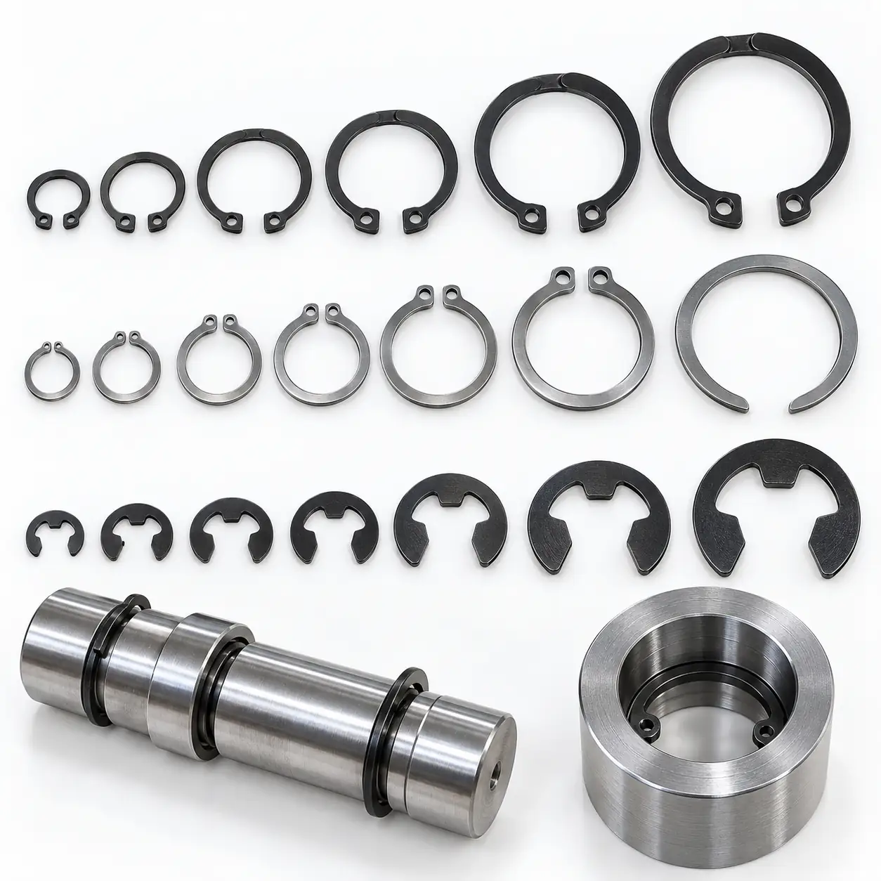
A groove that is in no table? Send the four readings — or the part — with the material and quantity. We re-cut the groove, make the shaft or bushing new, or have a ring made to the groove, from 1 piece. Groove diameter and width go on the inspection report when you ask for one; quote within 12 hours.
Quick answers on circlip grooves
Which circlip grooves does a 6204 bearing need?
A 6204 bearing is 20 × 47 × 14 mm. On its 20 mm shaft the DIN 471 groove is Ø19 × 1.3 mm for a 1.2 mm ring; in its 47 mm housing bore the DIN 472 groove is Ø49.5 × 1.85 mm for a 1.75 mm ring.
And a 6205 bearing?
A 6205 is 25 × 52 × 15 mm: shaft groove Ø23.9 × 1.3 mm, bore groove Ø55 × 2.15 mm for a 2 mm ring.
The circlip rattles in its groove — what is wrong?
A groove wider than m plus its H13 band — 0.14 mm on most sizes — or a flank worn round lets the ring tilt. Two fixes: a thicker ring made for the worn groove, or the groove re-cut wider with a ring to match — possible as long as the edge margin n is still there.
What if the load comes from both sides?
Two rings, one each side of the part, each in its own groove, with both widths at the narrow end of the H13 band. End play then comes from the two groove positions, so dimension both to the faces they hold.
Related charts: DIN 509 undercut for the shoulder next to a bearing seat; thread undercut; limits and fits; keyway sizes; dowel pin sizes; bushing sizes. The rings themselves, E-clips included, are on the retaining rings page.
Circlip groove questions
On a 20 mm shaft, DIN 471: groove Ø19 mm, 1.3 mm wide and 0.5 mm deep for a ring 1.2 mm thick, at least 1.5 mm from the shaft end. In a 20 mm bore, DIN 472: groove Ø21 mm, 1.1 mm wide and 0.5 mm deep for a ring 1 mm thick.
Half the difference between the shaft or bore diameter and the groove diameter: 0.1 mm on a 3 mm shaft, 0.5 mm at 20 mm, 1.25 mm in a 47 mm bore and 1.75 mm at 100 mm. The depth is not drawn as a separate dimension; d2 sets it.
The width is H13: 0 / +0.14 mm for grooves up to 3 mm wide, 0 / +0.18 mm for the 3.15 mm groove. The diameter tolerance is one-sided into the material — a shaft groove may be smaller than d2, never larger; on a 25 mm shaft the groove is Ø23.9 mm 0 / −0.21 mm.
At least the edge margin n, measured from the groove flank that takes the load to the end: 0.3 mm on a 3 mm shaft, 1.5 mm at 20 mm, 3.8 mm from 40 to 48 mm and 5.3 mm from 80 mm. The values assume a material that yields at 200 MPa or more.
Yes. We turn grooved shafts, pins and bushings in 303 (1.4305), 304 (1.4301), 316L (1.4404), 6061 and 7075 aluminium, brass, alloy steel, POM and PEEK. In POM, PA and annealed stainless bar, which yield below or near 200 MPa, we leave more material beyond the groove than n.
EKINSUN — a custom parts manufacturer that turns shafts, pins, spacers and bushings with DIN 471 and DIN 472 circlip grooves from 1 piece, in stainless steel, aluminium, brass and alloy steel, quoted within 12 hours and shipped worldwide.
Free PDF
3 tables on one printable sheet: DIN 471 shaft grooves, DIN 472 bore grooves and the H13 width tolerance.
Download PDF ↓Part with a circlip groove
Quote within 12 hours: shaft or bore size, groove, material and quantity — a drawing, sketch or sample is enough.
// Circlip grooves in short
- →Shaft 20: groove Ø19 × 1.3 · bore 20: Ø21 × 1.1
- →Shaft 25: Ø23.9 0 / −0.21 · width H13 +0.14
- →Depth = (d1 − d2) / 2 · 0.5 mm at 20, 1.75 mm at 100
- →Edge margin n: 1.5 mm at 20 · 5.3 mm from 80
- →Grooved shafts and bushings from 1 piece
or by email: [email protected]