A thermowell is the closed-end tube that screws into a pipe or vessel so a temperature sensor can sit in the process without touching the medium — and can be pulled out while the line stays under pressure. EKINSUN LTD is a custom parts manufacturer that machines thermowells, sensor bodies and probe housings from solid bar: drilled, turned, hex-milled and threaded to a drawing, to the old well, or to the sensor you already have.
If your well is a catalogue item — 3/4 NPT, 0.260 in bore, U 4-1/2 in, 316, tapered — buy it from stock: instrument distributors keep those sizes, and a distributor will always be cheaper than a one-off. The wells we make are the ones a catalogue does not list: an odd U-length to suit a sensor that is already installed, a metric thread on an imperial bore, a copy of a discontinued OEM well, or a stepped tip that has to match an existing probe.
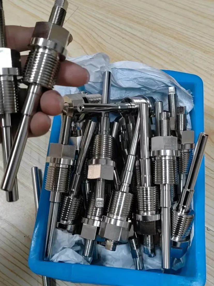
Thermowell U-Length Chart — and the Sensor Stem Each One Takes
The U-length is the part of the thermowell below the process thread — the length that sits in the medium — and a threaded well with U 4-1/2 in takes a 6 in thermometer or sensor stem when it has no lagging extension. The table lists the common threaded-well U-lengths with the stem length S that fits, without lag and with the standard lag T.
| U-length | Stem S, no lag | Standard lag T | Stem S with lag T |
|---|---|---|---|
| 2-1/2 in (63.5 mm) | 4 in (101.6 mm) | 2 in | 6 in (152.4 mm) |
| 4-1/2 in (114.3 mm) | 6 in (152.4 mm) | 3 in | 9 in (228.6 mm) |
| 7-1/2 in (190.5 mm) | 9 in (228.6 mm) | 3 in | 12 in (304.8 mm) |
| 10-1/2 in (266.7 mm) | 12 in (304.8 mm) | 3 in | 15 in (381 mm) |
| 13-1/2 in (342.9 mm) | 15 in (381 mm) | 3 in | 18 in (457.2 mm) |
| 16-1/2 in (419.1 mm) | 18 in (457.2 mm) | — | — |
| 19-1/2 in (495.3 mm) | — | 3 in | 24 in (609.6 mm) |
| 22-1/2 in (571.5 mm) | 24 in (609.6 mm) | — | — |
The rule behind the table: overall well length = U + T + the thread-and-hex length, and the instrument stem is 1/4 in shorter than the overall length. The thread-and-hex length is 1.75 in on Ashcroft threaded wells, while Pyromation catalogues give U = S − 1-1/2 in for their well length S. That 1/4 in between two makers is why a replacement well is measured, not looked up. The standard lag is 3 in, or 2 in on a 2-1/2 in U; lag lengths in 3 in steps keep the stem on a standard length.
// Stem length from U-length and lag (Ashcroft sizing rule)
Stem = U + T + thread-and-hex length − 1/4 in, as in Ashcroft's sizing example (U 4.50 + 1.75 = OAL 6.25, stem 6 in). Change the thread-and-hex length to the value you measure on your own well.
Thermowell Bore Size — Which Sensor Fits
The two standard bores of North American threaded wells are 0.260 in, for sensors up to 0.252 in (1/4 in) diameter, and 0.385 in, for sensors up to 0.377 in (3/8 in). DIN 43772 protection tubes come with metric bores of 6.1, 7 and 9 mm (WIKA TW 95.35).
| Bore | mm | Takes a sensor up to | Where you meet it |
|---|---|---|---|
| 0.260 in | 6.60 | 0.252 in (6.40 mm) — 1/4 in RTDs, thermocouples, bimetal stems | Standard-duty stepped, heavy-duty tapered and straight threaded wells |
| 0.385 in | 9.78 | 0.377 in (9.58 mm) — 3/8 in stems | Heavy-duty and straight wells, 3/4 NPT and larger |
| 7 mm | 7.0 | — | DIN 43772 Form 2G on 11 × 2 or 12 × 2.5 mm tube |
| 9 mm | 9.0 | — | DIN 43772 Form 2G on 14 × 2.5 mm tube |
| 6.1 mm | 6.1 | — | Third bore listed for DIN 43772 tubes in WIKA TW 95.35 |
On the inch sizes the clearance is 0.008 in (0.2 mm) on diameter — enough to slide the sensor in, close enough to keep the thermal lag down; Ashcroft describes the bore as "easy installation of the instrument, but a snug fit". A bore we drill for a sensor that is neither 1/4 nor 3/8 in follows the same logic: send the sensor diameter and the bore is set from it. The bore stops short of the tip: catalogue wells leave a 1/4 in (6.35 mm) solid tip.
Process Connection Threads — Identify the Old Well Before You Copy It
Threaded thermowells use 1/2, 3/4 or 1 NPT taper threads in North America and G 1/2, G 1 or M20 × 1.5 parallel threads on DIN 43772 wells, and each one can be told apart by its outside diameter and threads per inch.
| Thread | Outside Ø (mm) | TPI / pitch | Form | Typical on |
|---|---|---|---|---|
| 1/2 NPT | 21.336 | 14 TPI | 60° taper 1:16, seals on the thread | US threaded wells, process end |
| 3/4 NPT | 26.670 | 14 TPI | 60° taper | US threaded wells |
| 1 NPT | 33.401 | 11.5 TPI | 60° taper | US threaded wells |
| G 1/2 | 20.955 | 14 TPI | 55° parallel, seals on a washer or face | DIN 43772 wells |
| G 3/4 | 26.441 | 14 TPI | 55° parallel | DIN 43772 Form 2G |
| G 1 | 33.249 | 11 TPI | 55° parallel | DIN 43772 wells |
| M20 × 1.5 | 20.000 | 1.5 mm | 60° parallel | DIN 43772 wells |
| M24 × 1.5 | 24.000 | 1.5 mm | 60° parallel | Instrument end of DIN 43772 wells |
| 1/2 NPT female / 1/2 NPSM | — | 14 TPI | taper / straight | Instrument end of US wells |
1/2 NPT and G 1/2 are the pair that gets mixed up: 21.34 against 20.96 mm outside, both 14 threads per inch — they start by hand and lock after two turns. Measure the outside diameter over the crests with a caliper and count the threads over 1 in; on a taper thread, measure at the first full thread. The thread identification chart and the metric vs imperial thread chart cover the other sizes.
Straight, Tapered or Stepped Stem
A straight stem is the plain shape for low pressure and low velocity, a tapered stem is stiffer for the same tip and is the shape Ashcroft recommends for strength and vibration resistance, and a stepped stem thins the tip for a faster response.
| Stem | Root Ø Q — 1/2 / 3/4 / 1 NPT | Tip Ø V | Chosen for |
|---|---|---|---|
| Straight | 5/8 / 3/4 / 7/8 in | = root | Low pressure and velocity; 0.260 or 0.385 in bore |
| Tapered | 11/16 / 7/8 / 1-1/16 in | 5/8 in (0.260 bore); 49/64 in (0.385 bore, 3/4 and 1 NPT) | Flow and pressure where rigidity counts; tapered length up to 16 in |
| Stepped | 5/8 / 3/4 / 7/8 in | 1/2 in over the last 2-1/2 in | Faster response with a 0.260 in bore |
Which stem a process needs is a strength question — the wake-frequency and pressure check of ASME PTC 19.3 TW. That calculation is made by the plant's instrument engineer or the instrument supplier; we machine to the drawing that passed it and do not issue the calculation.
Metric Thermowells to DIN 43772
DIN 43772 is the German standard for thermowells and protection tubes; its threaded Form 2G (straight) and Form 3G (tapered) are built from tube closed by a welded tip, and a Form 2G tube has an overall length L = U1 + 145 mm — Schramm lists it with insertion lengths U1 of 160, 220 and 280 mm.
| Form | Tube Ø × wall → bore | Process thread | U1 → L (mm) | Source |
|---|---|---|---|---|
| 2G straight | 11 × 2 → 7 · 12 × 2.5 → 7 · 14 × 2.5 → 9 mm | G 1/2, G 3/4, G 1, 1/2 NPT | 160 → 305 · 220 → 365 · 280 → 425 | Schramm SR21 |
| 2G straight | bores 6.1, 7, 9 mm | G 1/2 B, G 1 B, M20 × 1.5, 1/2 NPT | L = U1 + 145 | WIKA TW35 |
| 3G tapered, fast response | bores 6.1, 7, 9 mm | G 1/2 B, G 1 B, M20 × 1.5, 1/2 NPT | L = U1 + 147 | WIKA TW35 |
The instrument end is M24 × 1.5 as standard, with G 1/2 or 1/2 NPT as options; the listed materials are 1.4571 (316Ti), 1.4404 (316L) and 1.4539 (904L). A protection tube built from tube and a thermowell drilled from bar are two constructions: we machine from solid bar. If the old part is a DIN 43772 tube, tell us — the thread, U1 and bore carry over, and the wall of the drilled well is agreed with you, not copied from the tube.
What We Machine — Thermowells, Probe Housings and Sensor Bodies
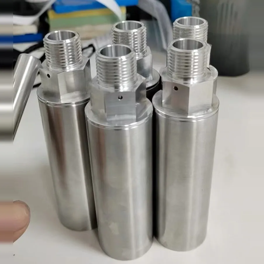
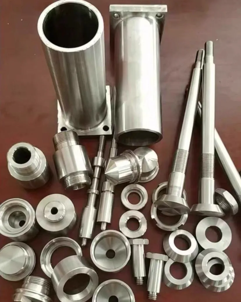
EKINSUN machines threaded thermowells, cylindrical sensor housings and probe bodies from solid bar, as single replacements or in batches, drilling the bore, turning the stem, milling the hex and cutting the process and instrument threads on one part.
- Bore: blind, drilled from bar, to the sensor diameter — 0.260 in, 0.385 in, 6.1, 7, 9 mm or your size.
- Stem: straight, tapered or stepped; U-length and lag to the millimetre you give us.
- Process end: NPT, G, metric or UNF thread, hex or wrench flats; weld-in and flanged versions to drawing.
- Instrument end: 1/2 NPT female, 1/2 NPSM, M24 × 1.5, G 1/2 female, or a thread matching your head.
- Housings: sensor bodies with a hex, cross holes, internal and external threads, bored to take a module.
- Materials: 304 (1.4301), 316L (1.4404), 1.4571, free-cutting 1.4305, brass, carbon steel; EN 10204 3.1 certificate on request.
Catalogue Well or Machined Well
A standard well from an instrument catalogue is the cheaper answer whenever one fits; the machined well is for the size, thread or copy that no catalogue lists.
| The well you need | In the catalogue? | What we do |
|---|---|---|
| 3/4 NPT, 0.260 in bore, U 4-1/2 in, 316, tapered | Yes | Buy it from stock — a distributor beats any one-off on price |
| DIN 43772 Form 2G in 1.4571, U1 160 / 220 / 280 mm | Yes | Buy it from stock |
| Brass well for a heating buffer tank, G 1/2 | Yes | Buy it from a heating wholesaler |
| Flanged well with a PTC 19.3 calculation | Yes, from instrument makers | Buy it there — we do not issue the calculation |
| Same well with U 6-3/16 in to fit a sensor that is already installed | No | Machined to length |
| G 1/2 or M20 × 1.5 thread on a 0.260 in bore | Rarely | Machined — metric thread, inch bore |
| Copy of a discontinued OEM well, thread unknown | No | Thread identified from the sample, well copied |
| Stepped tip to match an existing 6 mm probe | Sometimes | Machined to the probe |
| Bore for a 3 mm or 1/8 in sheathed sensor | Some makers | Quoted from the sensor diameter and bore depth |
What We Need for a Quote
A thermowell quote needs five numbers — process thread, U-length, lag, bore or sensor diameter, and stem shape — plus material and quantity, and with those we reply within 12 hours. A request that gets a price in one reply reads: "3/4 NPT, U 190 mm, bore for a 6 mm Pt100, stepped stem, 316L, 4 pieces."
No drawing? Send the old well, or a photo with a caliper across the thread and the stem, and the sensor you will put in it; we return a dimensioned drawing to approve before machining. Single replacement wells are made from 1 piece, and the price per piece falls with quantity. For the thread converters that sit between a well and a sensor head, see sensor thread adapters; for machined housings in general, custom machined housings.
Custom Thermowell FAQ
The U-length is measured from the underside of the process thread, or the flange face, to the tip — the part that sits in the pipe or vessel. On threaded wells the common U-lengths are 2-1/2, 4-1/2, 7-1/2, 10-1/2, 13-1/2, 16-1/2, 19-1/2 and 22-1/2 in (Ashcroft Bulletin TH-1).
For an Ashcroft threaded well the stem is U + lag + 1.75 in − 1/4 in: a well with U 4-1/2 in and no lag takes a 6 in stem, with a 3 in lag a 9 in stem. Other makers use a different thread-and-hex length, so on a replacement measure from the top of the instrument thread to the bottom of the bore.
0.260 in (6.60 mm), which takes sensors up to 0.252 in. A 3/8 in sensor needs 0.385 in (9.78 mm). For a metric probe, send its diameter and the bore is set from it.
No. 1/2 NPT is a 60° taper thread of 21.336 mm outside diameter; G 1/2 is a 55° parallel thread of 20.955 mm. Both have 14 threads per inch, so they start together by hand and jam after two turns.
No. The wake-frequency and pressure check belongs to the plant's instrument engineer or the instrument supplier. We machine the well to the drawing that passed that check and supply an EN 10204 3.1 material certificate on request.
Yes. Send the old well, or photos with a caliper across the thread, the hex and the stem, plus the sensor that goes into it. We identify the thread, measure the bore depth and the stem, and send a drawing to approve before machining.
EKINSUN LTD is a custom parts manufacturer that machines threaded thermowells, sensor housings and probe bodies to drawing or sample, from 1 piece, with a quote within 12 hours. If your size is a catalogue well, an instrument distributor is the cheaper source.
It depends on bore depth, material and quantity — a long, small bore in 316L costs more than a short one in 304 — so each well is quoted from its numbers within 12 hours; there is no list price. A catalogue well of a standard size costs less than a one-off.
Well Not in the Catalogue?
Odd U-length, metric thread on an inch bore, a discontinued OEM well — send thread, U-length and sensor diameter, or the old well. From 1 piece, quote within 12 hours.