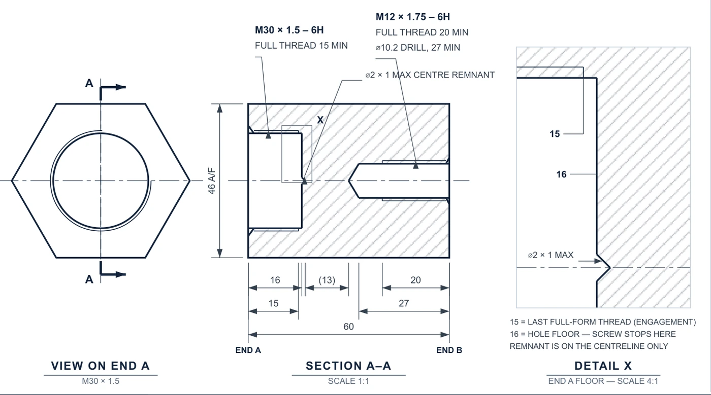
THE GEOMETRY FROM THE APPROVAL DRAWING ISSUED FOR THIS ENQUIRY · VIEW ON END A, FULL SECTION A–A, AND A 4:1 DETAIL OF THE END A FLOOR
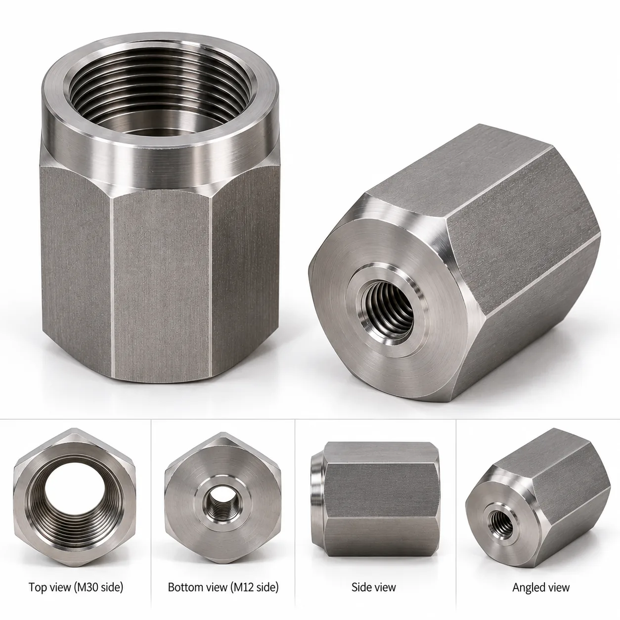
The Enquiry: Two Female Threads, One Hex Body, Quantity One
This enquiry arrived as a written specification with no drawing attached — a short list of numbers, which is a normal way to start. Condensed:
"Custom CNC metric thread adapter. Form: female-female coupler. End A: M30×1.5 female, fit class 6g, engagement 14–15 mm, physical bottom 16 mm (maximum screw insertion). End B: M12×1.75 female, engagement 20 mm. Hex body — what hex size would be used? Material 316 stainless. Overall length 60 mm (arbitrary). Use: mechanical only. Quantity 1 pc."
Nearly all of that is unusually precise for a first message. The customer separated engagement from physical bottom, said which dimensions he did not care about, and stated the duty. Three things still had to be settled before metal could be cut: the hex size he explicitly asked us to choose, one tolerance class that cannot exist on a female thread, and the depths that a drawing has to state but an enquiry rarely does.
EKINSUN LTD is a custom parts manufacturer — single parts and small batches machined to a customer's own specification through qualified manufacturing partners. Work starts from whatever the customer has: a written spec like this one, a hand sketch, a photo with a caliper in it, a worn original, or a STEP file. A dimensioned approval drawing goes back before anything is machined.
What a Catalogue Coupler Gives You — and Where It Stops
Female-female couplers are a stocked product. The table below marks the point where the catalogue stops being the cheaper answer.
| What you need | Stocked? | The route |
|---|---|---|
| A female-female coupler, same coarse thread both ends — M12 to M12, M16 to M16 | Yes — rod couplers and connector nuts are catalogue items in coarse metric | Buy the stocked coupler. It is cheaper than any one-off and we will say so |
| M30×1.5 fine at one end, M12×1.75 coarse at the other | No standard coupler pairs a fine 1.5 mm pitch with a coarse M12 | Machined from bar to the exact thread pair, quantity 1 |
| A stated engagement depth and a separate hard stop — 15 mm of thread over a floor at 16 mm | Not a property any coupler datasheet declares | Both depths dimensioned on the drawing and cut to it |
| 316 / 316L stainless rather than zinc-plated steel or brass | Rare — stocked couplers are mostly plated steel, brass or A2 | Bar grade chosen line by line, 316/316L to ASTM A276 |
| A hex sized to a spanner you already own | Whatever width across flats the stocked part happens to have | Across flats chosen from the nut standard for the thread |
| One piece, no tooling charge | Minimum pack quantities | MOQ 1, and a repeat is cheaper because the drawing is kept |
316 was the customer's call, and it is often the right one — but not always. 316 and 316L carry 2 to 3% molybdenum, and that is what buys resistance to chlorides, salt spray and coastal air; 304 has none of it. For a dry mechanical joint used indoors, 304 does the same structural job for noticeably less money, and the thread classes, depths and hex size on this drawing would not change at all. Where the adapter lives decides it: 316/316L for marine, coastal, pool-plant or chemical exposure, 304 for general indoor and structural duty. We quote the grade that is asked for, and say so when the cheaper one would have done.
"Fit Class 6g" on a Female Thread: the One Error in the Spec
6g is an external-thread class. In ISO 965 the case of the letter carries the meaning: lower-case letters (g, h, e) are external threads, upper-case letters (H, G) are internal threads. A bolt or stud is 6g; the nut thread it screws into is 6H. So a female M30×1.5 cannot be 6g — the class simply does not apply to it.
The likeliest reading is that the customer quoted the class of the mating male part, which is a reasonable thing to have on hand. It also happens to be the right answer: 6H/6g is the standard general-purpose fit pair, so a 6H internal thread is exactly what mates with the 6g stud he was thinking of, at the normal clearance. The drawing therefore says 6H at both ends, with the substitution written in a query block rather than made silently — a class change is the customer's call, not ours. The buyer confirmed 6H on 19 August 2026, accepting that the 6g in his enquiry was an error — which is how a spec query should close: raised before metal is cut, decided by the customer, recorded on the drawing.
The other half of the discipline is not "correcting" what is already right. M12×1.75 is the standard coarse pitch for M12, so it stays exactly as written. Only one of the two thread callouts in this enquiry needed touching. General dimensional tolerances are a separate system again, and threads are explicitly outside it — see the ISO 2768 general tolerance chart for where that boundary sits.
The spec moved once after the first drawing went out. The buyer lengthened End B engagement from 20 mm to 26 mm, which carries the ⌀10.2 tapping drill to 33 mm and leaves a 7 mm solid web between the two blind holes instead of 13 mm. That is ample for a mechanical joint, and it is worth saying out loud rather than letting the customer find it in the section view: on a 60 mm body, every millimetre of extra engagement at one end comes straight out of the web between the two bores.
Engagement 15 and Hole Floor 16 Are Not the Same Number
This is the part of the enquiry worth copying. The customer gave two depths for one hole, and they measure different things: engagement is how much thread carries load, and the floor is where the screw physically stops. A blind tapped hole needs both on the drawing, because stating one leaves the other undefined.
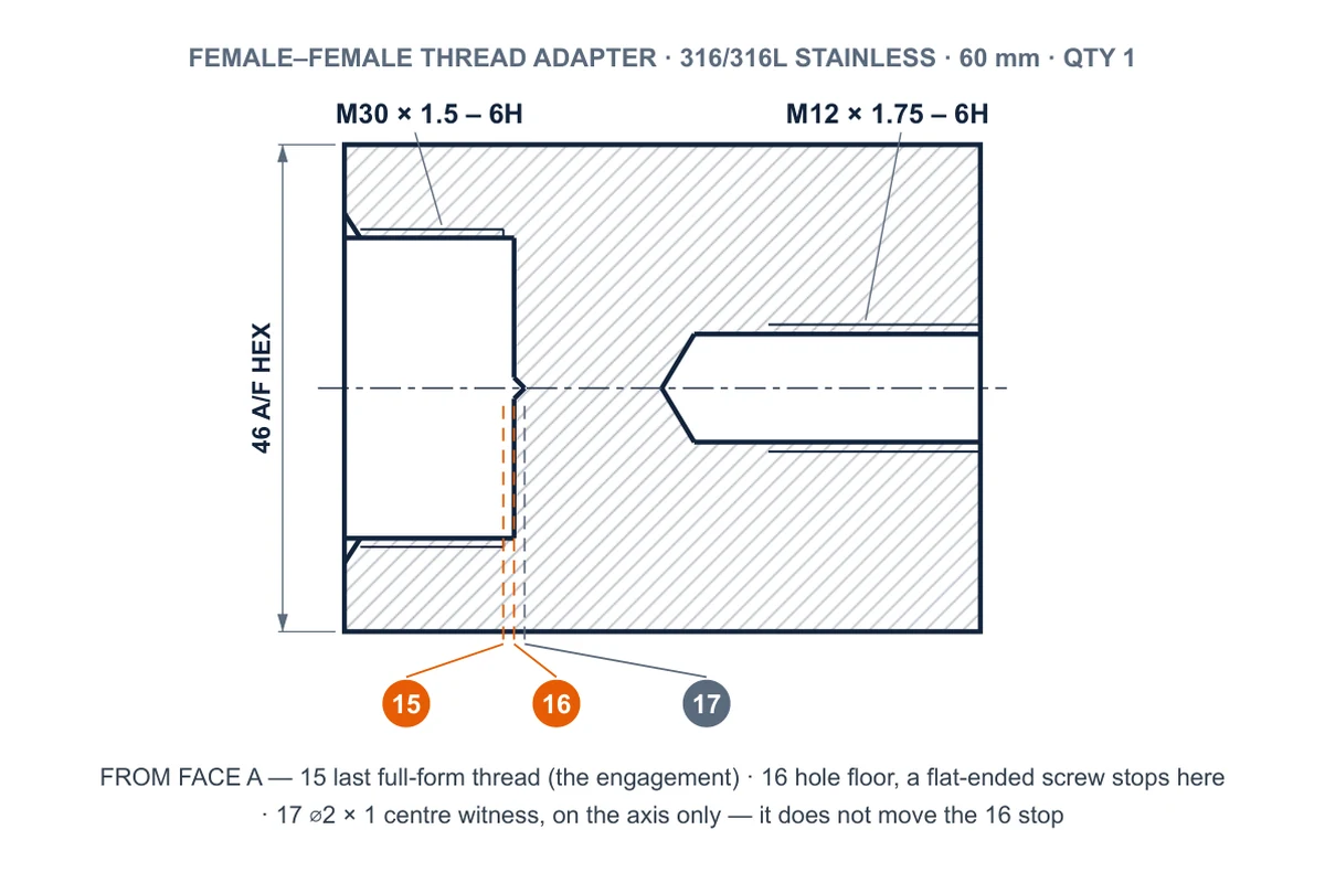
THE THREE END A DEPTHS SIT 1 MM APART · AT 1:1 THEY ARE INVISIBLE, WHICH IS WHY THE DRAWING CARRIES A 4:1 DETAIL OF THIS EXACT REGION
| Depth from the face | What it actually is | Who sets it |
|---|---|---|
| End A — 15 mm | Last full-form thread. This is the engagement: the length that carries load | Customer |
| End A — 16 mm | Hole floor. A flat-ended screw bottoms here, and goes no deeper | Customer |
| End A — 17 mm | Deepest point of the bore: a ⌀2 × 1 mm centre witness of the drill point, on the axis only | Manufacturing |
| End B — 20 mm | Last full-form thread of the M12×1.75 | Customer |
| End B — 27 mm | Drill depth: the 20 mm of thread plus 4 pitches of tap lead-in | Manufacturing |
| Web — 13 mm | Solid 316 left between the two blind bores. Nothing passes through the adapter | Falls out of the 60 mm length |
The 17 mm figure is the one that looks alarming and is not. A boring bar sweeps a circle and cannot cut the centre of a flat bottom, so a small witness of the drill point survives in the floor. Written as a maximum of 2 mm diameter by 1 mm deep, it does not move the customer's stop: an M30 screw presents a solid end face around 28 mm across and seats on the flat ring outside the witness, still at 16 mm. The bore's deepest point is 17 mm, but nothing that fits an M30×1.5 thread can reach it.
Why That 1 mm Rules Out a Tap — and Why End B Is Different
A tap cannot produce full thread to within 1 mm of a blind floor. The tip of a tap carries a chamfer that cuts a partial form — 3 to 5 threads on a plug tap, 1 to 1.5 on a bottoming tap — so a tapped hole always loses several pitches of depth below the last full thread. On M30×1.5 that is 4.5 to 7.5 mm. Tapping this hole to a 16 mm floor would have left full thread ending somewhere near 11 mm, well short of the 15 mm asked for.
Thread milling into a flat-bottom bore solves it. A thread mill is a smaller tool orbiting the bore, so it can cut full form to within roughly 1 mm of the floor and leave the floor flat and square for the screw to seat on. That is the whole reason End A is milled rather than tapped: the two numbers the customer gave — 15 mm of thread and a hard stop at 16 mm — cannot coexist any other way.
End B is the opposite case, and gets the ordinary treatment. There the customer specified engagement only and said nothing about a floor, so the depth of the hole is ours to choose and there is no reason to buy an expensive process. It is drilled 27 mm — 20 mm of thread plus 7 mm, four pitches of M12×1.75, for the tap lead-in and chip room — and tapped. The rule worth taking away: specify a hard stop only where the design needs one, because pinning the floor is what forces the more expensive process.
What Hex Size an M30 Adapter Should Be
The customer asked this outright, and the deciding factor is not strength — it is the spanner. Every candidate below is strong enough for mechanical duty; the question is what fits the wrench already in the toolbox and how much wall survives over the M30 thread.
| Hex across flats | Wall over the M30 thread | Mass at 60 mm | Verdict |
|---|---|---|---|
| 36 mm | 3.0 mm | ≈432 g | Too thin. A 316 ring this light deflects and chatters while the thread is cut |
| 41 mm | 5.5 mm | ≈592 g | Works, and it is the light option — a standard 41 mm socket size |
| 46 mm | 8.0 mm | ≈772 g | Chosen. The ISO 4032 / DIN 934 width across flats for an M30 nut, so an M30 spanner fits |
| 50 mm | 10.0 mm | ≈932 g | More bar removed and more weight for no functional gain |
46 mm across flats is the standard hex nut width for M30 in both ISO 4032 and DIN 934, which makes it the answer that needs no explanation on site: anyone already working with M30 hardware owns the spanner. Across corners it measures 53.1 mm, and the adapter is made from 46 mm hex bar rather than milled from round, which keeps a one-off cheap. The same across-flats logic drives our large custom nuts, where the nut width and the customer's tooling have to agree.
What This Case Generalises To
The specific pair is M30×1.5 to M12×1.75, but the pattern behind it is ordinary: a coupler whose two ends belong to different thread families, in a material the catalogue does not stock, with a depth requirement that a datasheet has no field for. Mixed pitches, metric to imperial, a fine thread against a coarse one, or a stainless grade chosen for the environment rather than for price — each on its own is enough to leave the catalogue behind.
If you need a specific pair joined, start at connecting two different threads or browse custom metric thread adapters for the sizes already documented. If what you have is a sketch or a photo rather than numbers, ordering from a hand drawing describes how that turns into an approval drawing, and drawings you send are covered by our NDA and confidentiality policy. Quantity one is a normal order, and so is a framework order for a few hundred off the same kept drawing.
Two internal threads is one of three forms. The male-female M24×2 to M20×1.5 in 304 has one of each, and the double-male M35×1.5 to M30×2 in 316L has two external — same hex body, same one-piece turning.
Frequently Asked Questions
No. In ISO 965 a lower-case letter is an external thread and an upper-case letter is an internal thread, so 6g belongs to a bolt or stud and 6H is the internal equivalent. 6H/6g is the standard general-purpose pair: a 6H nut thread and a 6g bolt thread are designed to go together. An enquiry that asks for a female thread at 6g almost always means 6H, or has quoted the class of the mating male part. We draw it as 6H and flag the change rather than changing it silently.
Thread engagement is the length of full-form thread that carries load. Hole depth is where the bore physically ends. On this adapter they are 15 mm and 16 mm from the same face: a screw is supported by thread over the first 15 mm and then bottoms on the floor at 16 mm. The 1 mm between them is thread run-out. Quoting only one number leaves the other undefined, which is why a blind tapped hole needs both on the drawing.
46 mm across flats. That is the standard width across flats for an M30 hex nut in ISO 4032 and DIN 934, so any 46 mm socket or spanner already bought for M30 hardware fits the adapter. It also leaves an 8.0 mm wall over the M30 thread. 41 mm across flats works and saves about 180 g, while 36 mm leaves only a 3.0 mm wall, which is thin enough in 316 for the ring to deflect while the thread is being cut.
About 27 mm if the thread is cut with a tap. A plug tap carries a chamfer of 3 to 5 threads that does not cut full form, which at the 1.75 mm pitch of M12 coarse is 5.25 to 8.75 mm of lead-in. Adding 4 pitches, or 7 mm, to the 20 mm of required thread gives a 27 mm drill depth and leaves room for chips in a blind hole. If the thread is milled instead, roughly 22 mm is enough.
Not with a tap, but yes with a thread mill. A tap needs 3 to 4 pitches of run-out below the last full thread, so a tapped M30×1.5 hole with a floor at 16 mm would only carry full thread to about 11 or 12 mm. Thread milling into a flat-bottom bore produces full form to within roughly 1 mm of the floor, which is how this part holds 15 mm of thread and a hard stop at 16 mm at the same time.
No, provided it is small and stays on the axis. A boring bar cannot cut to the centre of a flat bottom, so a witness of the drill point up to 2 mm diameter and 1 mm deep is normal and is written on the drawing as a maximum. An M30 screw presents a solid end face of roughly 28 mm diameter, so it seats on the flat ring outside the witness and still stops at the specified 16 mm. The deepest point of the bore is 17 mm, but nothing that fits the thread can reach it.
EKINSUN — a custom parts manufacturer that machines one-off and low-volume adapters to a thread pair you name, MOQ 1 up to production batches, with a quote in 12 hours. If both ends of your coupler are common coarse metric sizes, a stocked coupler is cheaper and we will say so. Mixed pitches, mixed standards, 316 stainless, or a stated engagement depth and hard stop are the cases where no catalogue part exists.
MOQ 1 to production volume, no tooling charge. One adapter to prove the thread pair, a batch from the same kept drawing when the design settles. Quote in 12 hours; typical production 5 working days after drawing approval.