A DIN 509 undercut — in ISO wording a relief groove — is the small groove turned into the corner where a shaft steps down, so the grinding wheel can run up to the shoulder and a bearing, hub or bush pushed on the shaft sits flat against the shoulder instead of riding on the corner radius. Its size r × t1 follows the shaft diameter d1 and the load: the charts below give every size of types E, F, G and H with tolerances and the minimum countersink on the mating part.
// Undercut finder — enter the shaft diameter d1
| Undercut | Series | f | t2 | g ≈ | Min. a |
|---|
Series 1 radii are preferred. The diameter ranges do not apply to short shoulders or thin-walled parts; on a part with several diameters one undercut size for all shoulders can be the cheaper choice.
EKINSUN LTD is a custom parts manufacturer that turns stepped shafts, axles and pins to drawing, with DIN 509 undercuts at the ground shoulders, from 1 piece. A plain precision shaft — h6 linear shaft cut to length, no shoulders — is cheaper in the catalogue: buy it off the shelf. We make the stepped shaft that is not on the shelf.
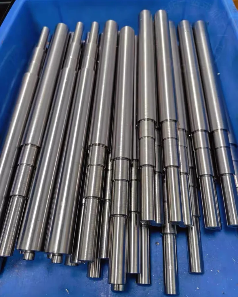
DIN 509 Undercut Chart — Types E and F
Type E is the undercut for a cylindrical surface that is machined afterwards — ground, as a rule — while the shoulder face carries little load; type F is used when both the cylinder and the shoulder face are machined, and adds the face depth t2.
| r | Series | t1 | f | t2 (F) | g ≈ (F) | d1, normal load | d1, higher fatigue load | Designation |
|---|---|---|---|---|---|---|---|---|
| 0.2 | 2 | 0.1 | 1 | 0.1 | (0.9) | over 1.6 to 3 | — | E/F 0.2 × 0.1 |
| 0.4 | 1 | 0.2 | 2 | 0.1 | (1.1) | over 3 to 18 | — | E/F 0.4 × 0.2 |
| 0.6 | 2 | 0.2 | 2 | 0.1 | (1.4) | over 10 to 18 | — | E/F 0.6 × 0.2 |
| 0.6 | 2 | 0.3 | 2.5 | 0.2 | (2.1) | over 18 to 80 | — | E/F 0.6 × 0.3 |
| 0.8 | 1 | 0.3 | 2.5 | 0.2 | (2.3) | over 18 to 80 | — | E/F 0.8 × 0.3 |
| 1 | 2 | 0.2 | 2.5 | 0.1 | (1.8) | — | over 18 to 50 | E/F 1 × 0.2 |
| 1 | 2 | 0.4 | 4 | 0.3 | (3.2) | over 80 | — | E/F 1 × 0.4 |
| 1.2 | 1 | 0.2 | 2.5 | 0.1 | (2) | — | over 18 to 50 | E/F 1.2 × 0.2 |
| 1.2 | 1 | 0.4 | 4 | 0.3 | (3.4) | over 80 | — | E/F 1.2 × 0.4 |
| 1.6 | 1 | 0.3 | 4 | 0.2 | (3.1) | — | over 50 to 80 | E/F 1.6 × 0.3 |
| 2.5 | 1 | 0.4 | 5 | 0.3 | (4.8) | — | over 80 to 125 | E/F 2.5 × 0.4 |
| 4 | 1 | 0.5 | 7 | 0.3 | (6.4) | — | over 125 | E/F 4 × 0.5 |
The smallest size, 0.2 × 0.1, belongs to shafts from 1.6 mm to 3 mm; the largest, 4 × 0.5, to shafts over 125 mm. Series 1 radii — 0.4, 0.8, 1.2, 1.6, 2.5 and 4 mm — are preferred; 0.2, 0.6 and 1 mm are series 2. Values in brackets are approximate. The diameter ranges do not apply to short shoulders or thin-walled parts, and on a part with several diameters one undercut size for all shoulders can be the cheaper choice.
Types G and H — Undercuts Cut with Indexable Inserts
Type G has a small transition angle and is only for workpieces without high fatigue loads; type H is type F with a larger transition angle — and both are sized so that a standard indexable insert to ISO 6987 cuts them, a rhombic insert for G and a triangular insert for H.
| Type | r | t1 | t2 | f ≈ | g ≈ | d1, normal load | d1, higher fatigue load | Designation |
|---|---|---|---|---|---|---|---|---|
| G | 0.4 | 0.2 | 0.2 | (0.9) | (1.1) | over 3 to 18 | — | G 0.4 × 0.2 |
| H | 0.8 | 0.3 | 0.05 | (2.0) | (1.1) | over 18 to 80 | — | H 0.8 × 0.3 |
| H | 1.2 | 0.3 | 0.05 | (2.4) | (1.5) | — | over 18 to 50 | H 1.2 × 0.3 |
The 2006 edition of DIN 509 corrected three of these values: f for type G from 1 to 0.9, g for G 0.4 × 0.2 from 1.2 to 1.1, and f for H 1.2 × 0.3 from 2.5 to 2.4. Charts copied from the 1998 edition still show the old numbers.
Undercut Tolerances
DIN 509 tolerances the undercut at r ± 0.1 mm, t1 + 0.1 mm, f + 0.2 mm and t2 + 0.05 mm, each with a lower deviation of 0, so the depth and width may come out larger than the chart value but never smaller.
| Dimension | Limit deviation | Checked with |
|---|---|---|
| r — radius | ± 0.1 mm | Radius gauge or optical comparator |
| t1 — depth into the cylinder | +0.1 / 0 mm | Diameter at the groove bottom against d1 |
| f — width along the cylinder | +0.2 / 0 mm | Caliper or comparator |
| t2 — depth into the shoulder (F, G, H) | +0.05 / 0 mm | Depth from the shoulder face |
DIN 509:2022-12 now carries the limit deviations as a supplement to DIN EN ISO 18388; on a drawing that cites the 2022 edition, its table applies. The dimensions apply to bores by analogy — an internal undercut in a bush or housing uses the same r × t1.
Countersink on the Mating Part — Minimum a
A part that must sit against a shoulder with an undercut — bearing ring, hub, gear, bush — needs a 90° countersink or chamfer of at least a, or it lands on the undercut radius instead of the face; the countersink diameter is d2 = d1 + 2a.
| Undercut r × t1 | Type E | Type F | Type G | Type H |
|---|---|---|---|---|
| 0.2 × 0.1 | 0.2 | 0 | — | — |
| 0.4 × 0.2 | 0.3 | 0 | 0 | — |
| 0.6 × 0.2 | 0.5 | 0.15 | — | — |
| 0.6 × 0.3 | 0.4 | 0 | — | — |
| 0.8 × 0.3 | 0.6 | 0.05 | — | 0.35 |
| 1.0 × 0.2 | 0.9 | 0.45 | — | — |
| 1.0 × 0.4 | 0.7 | 0 | — | — |
| 1.2 × 0.2 | 1.1 | 0.6 | — | — |
| 1.2 × 0.3 | — | — | — | 0.65 |
| 1.2 × 0.4 | 0.9 | 0.1 | — | — |
| 1.6 × 0.3 | 1.4 | 0.6 | — | — |
| 2.5 × 0.4 | 2.2 | 1.0 | — | — |
| 4.0 × 0.5 | 3.6 | 2.1 | — | — |
Worked example: a 30 mm shaft with F 0.8 × 0.3 needs a ≥ 0.05 mm on the mating part, so d2 ≥ 30.1 mm; with E 0.8 × 0.3 the same part needs a ≥ 0.6 mm, d2 ≥ 31.2 mm. Type F cuts into the shoulder, which is why its mating chamfer is smaller.
How to Write It on the Drawing
On a drawing the undercut is either fully dimensioned or given in simplified form with a leader line and its designation, for example “Undercut DIN 509 – E 1.2 × 0.2” or, in ISO form, “Relief groove ISO 18388 – E 1.2 × 0.2”.
The letter is the type, the first number the radius r and the second the depth t1; f, g and t2 follow from the chart, so they are not written on the drawing. A drawing that says only “undercut” with no type and size leaves the choice to the turner — say which type you need where a bearing or hub seats on the shoulder.
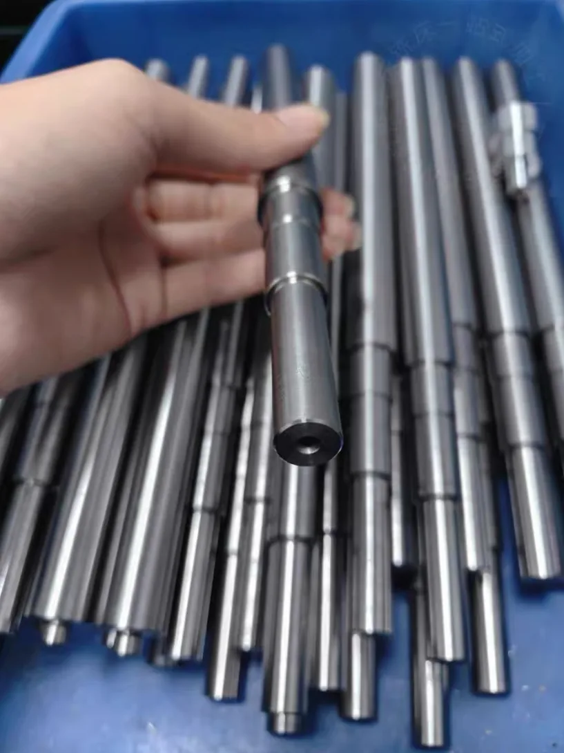
What It Is Called — and What It Is Not
The same groove is called an undercut, relief groove or grinding relief in English, Freistich in German and gorge de dégagement in French; a thread undercut at the end of a thread is a different feature, sized by the thread pitch in DIN 76-1 and ISO 4755.
| Feature | Shaft undercut (DIN 509 / ISO 18388) | Thread undercut (DIN 76-1 / ISO 4755) |
|---|---|---|
| Where | Shoulder of a shaft or bore that is ground or seated against | End of a thread next to a shoulder |
| Sized by | Diameter d1 and load | Thread pitch P |
| Written as | DIN 509 – E 0.6 × 0.3 | DIN 76-1 type A–D, or the groove width and diameter |
| Purpose | Grinding run-out, flat seating of the mating part | Full thread up to the shoulder |
For the thread version see the thread undercut chart.
When the Shaft Needs More Than the Chart
The chart sizes the groove; the shaft around it — diameters, fits, keyways, heat treatment — is where a stepped shaft becomes a drawing part.
| The shaft you need | In the catalogue? | What we do |
|---|---|---|
| Precision shaft h6 cut to length, no shoulders | Yes | Buy it off the shelf — cheaper in the catalogue |
| Stepped shaft to drawing, two ground k6 bearing seats, F 0.6 × 0.3 at each | No | Turned, seats ground, undercuts to the chart |
| Replacement shaft from a worn sample, undercut size unknown | No | r and t1 measured on the sample and put on our drawing for you to approve |
| Internal undercut in a bore (bush, housing) | No | Same r × t1 by analogy, plunge-turned in the bore |
| Shaft under alternating load, 42CrMo4 quenched and tempered | No | Higher-fatigue sizes (1.6 × 0.3 to 4 × 0.5), material certificate on request |
| Stainless shaft, 304 / 1.4301, 316L / 1.4404 or free-cutting 1.4305 | No | Turned to drawing in the grade you name |
| Non-standard undercut drawn by the designer | No | Machined to the drawing |
Shaft materials we turn: C45 / 1045, 42CrMo4 / 4140, 304 / 1.4301, 316L / 1.4404, free-cutting 1.4305, brass and 6061 or 7075 aluminium. Fits for the seats next to the undercut are on the limits and fits chart, general tolerances on the ISO 2768 chart, and the finish on the ground seat on the surface roughness chart. Quote within 12 hours from a drawing, a sketch or the old shaft.
A shaft with a ground bearing seat usually carries a circlip groove beside it — the DIN 471 groove sizes are in the circlip groove size chart.
The part that needs this groove most often is a shoulder bolt: the undercut at the step from shoulder to thread is on the drawing of every custom shoulder bolt we machine to a shoulder diameter the catalogue does not list.
DIN 509 Undercut FAQ
An undercut of type E with radius r = 0.6 mm and depth t1 = 0.3 mm. The chart then gives width f = 2.5 mm and the diameter range over 18 to 80 mm for normal loads.
If only the cylindrical seat is ground, type E; if the seat and the shoulder face are both ground, type F. For shafts under alternating load use the sizes of the higher-fatigue column, for example F 1.2 × 0.2 for d1 over 18 to 50 mm.
Yes, as DIN 509:2022-12. Since 2020 the types and dimensions sit in DIN EN ISO 18388 (ISO 18388:2016), and DIN 509:2022 adds the limit deviations and surface recommendations. The designation “DIN 509 – E 0.6 × 0.3” stays in use on drawings.
Normal load: E or F 0.8 × 0.3 (series 1) or 0.6 × 0.3 (series 2). Higher alternating load: 1.2 × 0.2 (series 1) or 1 × 0.2. A part seated on the shoulder needs a countersink a of at least 0.05 mm with F 0.8 × 0.3, or 0.6 mm with E 0.8 × 0.3.
Yes. The figures show shafts, and the same dimensions apply to bores by analogy; ISO 18388 states that its values are used for holes and shafts.
The 1998 edition listed f = 1 and g = 1.2 for G 0.4 × 0.2 and f = 2.5 for H 1.2 × 0.3. DIN 509:2006 corrected these to 0.9, 1.1 and 2.4, and ISO 18388 carries the corrected values.
EKINSUN LTD is a custom parts manufacturer that turns stepped shafts, axles and pins with DIN 509 undercuts to drawing or sample, bearing seats ground, from 1 piece, with a quote within 12 hours. A plain precision shaft with no shoulders is cheaper in the catalogue.
Length, number of shoulders, material and quantity set the price; the undercut is plunged in the same setup as the shoulder it relieves. Each shaft is quoted from its drawing or sample within 12 hours, with no list price.
Need the Shaft Too?
Stepped shafts, axles and pins with DIN 509 undercuts, bearing seats ground, from 1 piece. Drawing, sketch or the old shaft is enough.