// Reference · Keys & Keyways

Keyway Size Chart — Key Width, Height and Depth by Shaft Diameter

A 25 mm shaft takes an 8 × 7 mm parallel key: the shaft keyway is 4.0 mm deep, the hub keyway 3.3 mm deep, and the dimension you actually measure — shaft diameter minus keyway depth, d − t1 — is 21.0 mm. In inch practice a 1 in shaft takes a 1/4 in square key seated 1/8 in deep in both shaft and hub. The two charts below cover shafts of 6–500 mm to DIN 6885-1 and 5/16–6-1/2 in to ANSI B17.1; after them comes what the tables leave out: which tolerance to write on the drawing, and what to do when the keyway is worn or the shaft is not a catalogue size.

Download the chart as PDF ↓

Metric Keyway Size Chart — DIN 6885-1 Parallel Keys

DIN 6885-1 (high form) fixes the key section b × h from the shaft diameter, the keyway depth t1 in the shaft and t2 in the hub. ISO 773 and BS 4235 list the same sections and depths, so a German, a British and an ISO drawing agree on the numbers. The d − t1 column is the check dimension a caliper reads, given at the top of each diameter step; the last column is the key-length range the standard lists for that section.

Parallel key and keyway dimensions in mm — DIN 6885-1 high form (sections identical to ISO 773 / BS 4235)
Shaft Ø dKey b × ht1 shaft deptht2 hub depthd − t1 check dim.Back clearanceKey lengths
over 6 to 82 × 21.216.8 (at Ø8)0.26–20
over 8 to 103 × 31.81.48.2 (at Ø10)0.26–36
over 10 to 124 × 42.51.89.5 (at Ø12)0.38–45
over 12 to 175 × 532.314 (at Ø17)0.310–56
over 17 to 226 × 63.52.818.5 (at Ø22)0.314–70
over 22 to 308 × 743.326 (at Ø30)0.318–90
over 30 to 3810 × 853.333 (at Ø38)0.322–110
over 38 to 4412 × 853.339 (at Ø44)0.328–140
over 44 to 5014 × 95.53.844.5 (at Ø50)0.336–160
over 50 to 5816 × 1064.352 (at Ø58)0.345–180
over 58 to 6518 × 1174.458 (at Ø65)0.450–200
over 65 to 7520 × 127.54.967.5 (at Ø75)0.456–220
over 75 to 8522 × 1495.476 (at Ø85)0.463–250
over 85 to 9525 × 1495.486 (at Ø95)0.470–280
over 95 to 11028 × 16106.4100 (at Ø110)0.480–320
over 110 to 13032 × 18117.4119 (at Ø130)0.490–360
over 130 to 15036 × 20128.4138 (at Ø150)0.4100–400
over 150 to 17040 × 22139.4157 (at Ø170)0.4100–400
over 170 to 20045 × 251510.4185 (at Ø200)0.4110–450
over 200 to 23050 × 281711.4213 (at Ø230)0.4125–500
over 230 to 26056 × 322012.4240 (at Ø260)0.4140–500
over 260 to 29063 × 322012.4270 (at Ø290)0.4160–500
over 290 to 33070 × 362214.4308 (at Ø330)0.4180–500
over 330 to 38080 × 402515.4355 (at Ø380)0.4200–500
over 380 to 44090 × 452817.4412 (at Ø440)0.4220–500
over 440 to 500100 × 503119.5469 (at Ø500)0.5250–500

Ranges read “over – to”: a 30 mm shaft is the top of the 22–30 step and takes 8 × 7; a 22 mm shaft is the top of 17–22 and takes 6 × 6. Back clearance = t1 + t2 − h, the gap between the key top and the hub keyway bottom — the key carries on its flanks, never on its back. DIN 6885-3 (low form) uses shallower depths and is not interchangeable with this chart.

Standard key lengths run in one series for every section: 6, 8, 10, 12, 14, 16, 18, 20, 22, 25, 28, 32, 36, 40, 45, 50, 56, 63, 70, 80, 90, 100, 110, 125, 140, 160, 180, 200, 220, 250, 280, 320, 360, 400, 450, 500 mm. A key is cut from this series; a length between two steps — 33 mm, say — is a machined key, not a stock one.
Inch Keyway Size Chart — ANSI B17.1 Square and Rectangular Keys

ANSI B17.1 sizes the key from the shaft diameter in the same way, but the keyseat depth is defined differently from the metric chart: each member is cut half the key height deep, so a 1/4 in square key sits 1/8 in in the shaft and 1/8 in in the hub. Square keys are the preferred form through 6-1/2 in shafts; rectangular keys are used where the hub wall is thin. In the usual Class 2 fit the keyseat width is held to the key width +0.002 in / −0.000 in, and the key stock itself is bought slightly oversize and fitted.

ANSI B17.1 key size versus shaft diameter, inches (decimal in brackets)
Shaft Ø dSquare key W × HKeyseat depth, shaft and hubRectangular key W × HDepth, rectangular
over 5/16 to 7/163/32 × 3/32 (0.094)3/64 (0.047)
over 7/16 to 9/161/8 × 1/8 (0.125)1/16 (0.062)1/8 × 3/323/64 (0.047)
over 9/16 to 7/83/16 × 3/16 (0.188)3/32 (0.094)3/16 × 1/81/16 (0.062)
over 7/8 to 1-1/41/4 × 1/4 (0.25)1/8 (0.125)1/4 × 3/163/32 (0.094)
over 1-1/4 to 1-3/85/16 × 5/16 (0.312)5/32 (0.156)5/16 × 1/41/8 (0.125)
over 1-3/8 to 1-3/43/8 × 3/8 (0.375)3/16 (0.188)3/8 × 1/41/8 (0.125)
over 1-3/4 to 2-1/41/2 × 1/2 (0.5)1/4 (0.25)1/2 × 3/83/16 (0.188)
over 2-1/4 to 2-3/45/8 × 5/8 (0.625)5/16 (0.312)5/8 × 7/167/32 (0.219)
over 2-3/4 to 3-1/43/4 × 3/4 (0.75)3/8 (0.375)3/4 × 1/21/4 (0.25)
over 3-1/4 to 3-3/47/8 × 7/8 (0.875)7/16 (0.438)7/8 × 5/85/16 (0.312)
over 3-3/4 to 4-1/21 × 1 (1)1/2 (0.5)1 × 3/43/8 (0.375)
over 4-1/2 to 5-1/21-1/4 × 1-1/4 (1.25)5/8 (0.625)1-1/4 × 7/87/16 (0.438)
over 5-1/2 to 6-1/21-1/2 × 1-1/2 (1.5)3/4 (0.75)1-1/2 × 11/2 (0.5)

Metric and inch keys do not mix: 1/4 in = 6.35 mm, 3/8 in = 9.525 mm, 1/2 in = 12.7 mm. A 3/8 in key in a 10 mm keyway rocks by 0.475 mm and hammers the flanks out; a 10 mm key does not enter a 3/8 in keyseat at all. When a machine has one of each, the shaft is cut for the key that exists — see the repair table below.

Keyway Tolerances — Which Fit to Write on the Drawing

The key is the constant and the keyway carries the fit: the key width is h9 in every case, and the three fits differ only in the tolerance class written on the shaft and hub keyway widths. That is why an N9 keyway and a P9 keyway take the same key from the same box, and why writing just “8 mm keyway” on a drawing leaves the fit to chance.

Keyway width tolerance classes for parallel keys (DIN 6885-1 / ISO 773)
FitShaft keyway widthHub keyway widthKey widthWhen to specify it
Sliding fitH9D10h9The hub has to slide axially on the shaft — feather keys under shifting gears and sliding clutches.
Normal fitN9JS9h9The default for one-direction drives: the key is fitted by hand, does not walk, and comes out again for service.
Tight fitP9P9h9Reversing drives, shock and alternating loads: the key is pressed into the shaft and stays there; the hub is driven on.

Keyway depths t1 and t2 carry a plus tolerance only — the standard adds 0.1 to 0.2 mm above nominal depending on the section — because a keyway that is too deep only increases back clearance, while one that is too shallow lifts the hub off the shaft. The width is where a wrong number costs money: a keyway cut 0.05 mm wide on an 8 mm N9 flank is a key that hammers.

What Belongs on a Keyway Drawing — and What Is Usually Missing

The check dimension d − t1, not only t1. Keyway depth is defined from a theoretical shaft crest that has been milled away; nobody can measure it directly. A 25 mm shaft with t1 = 4.0 mm is dimensioned 21.0 mm from keyway bottom to the opposite surface, and that is the number checked on the machine with a caliper or a depth micrometer.

A symmetry tolerance of the keyway to the shaft axis. Without it, a keyway cut 0.1 mm off centre still meets the width and depth — and the hub sits off-centre, the key bears on one flank only, and a coupling that was balanced runs out. The same applies to the hub keyway relative to the bore.

Length, position and end form of the keyway. Where the keyway starts from the shaft end, how long it is, and whether it ends round (milled with an end mill, for a Form A round-ended key) or runs out (cut with a side-and-face cutter or on a keyseater, for a Form B square-ended key). A round-ended keyway is milled in one set-up; a run-out keyway on a shoulder cannot be.

The key material and length. Stock keys are C45 (1045) in the length series above; a key that must be 316 stainless, or 33 mm long, or stepped for a repaired keyway, is a made part — see custom machine keys, parallel, Woodruff, gib-head and oversized for worn keyways.

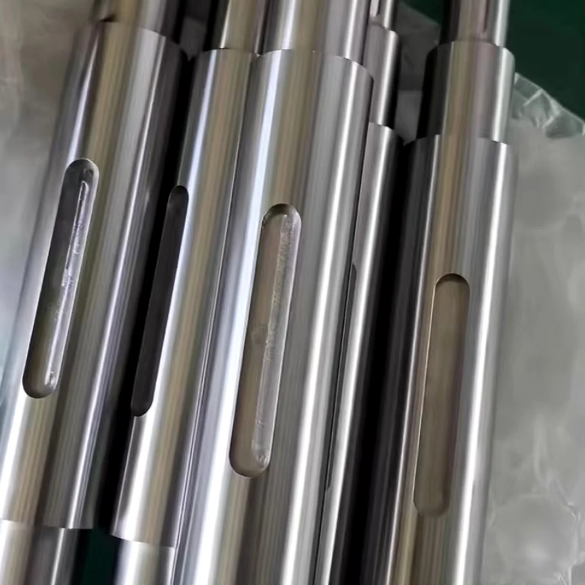
Batch of precision keyed shafts with milled parallel keyways, machined by EKINSUN
Keyed shafts, batch of 40 — keyway to N9, seats to h6, milled and turned in one set-up sequence

Materials for Keyed Shafts, Hubs and Keys

Materials we machine keyed parts from, and what each is for
MaterialUsed forWhat to know before you specify it
C45 / 1045 (1.0503)Stock keys, general shaftsAround 600 MPa tensile normalised; the key material the standard assumes, so key and shaft wear together instead of one destroying the other.
42CrMo4 / 4140 (1.7225)High-torque and reversing shaftsQuenched and tempered to 900–1100 MPa; a P9 keyway in 42CrMo4 holds its flanks where C45 would hammer out.
304 (1.4301)Food, washdown, general stainlessSofter than C45 — specify the key in 304 too, or a steel key gradually broadens the keyway.
316 / 316L (1.4404)Marine, chemical, medical drivesMachines to h6 and N9 without difficulty; galling on stainless-on-stainless keys is avoided with a light interference and no sliding.
6061-T6Light hubs, pulleys, sensor adaptersAn aluminium hub keyway bears roughly a third of the flank pressure of steel — use a steel key, a longer key or a larger section, not the table minimum.
7075-T6High-strength aluminium hubs and couplingsClose to mild steel in strength but not in bearing; the same longer-key rule applies, and no welding repair later.

Where the Chart Stops — Worn Keyways, Odd Shafts and Keys No Catalogue Lists

EKINSUN LTD is a custom parts manufacturer: keyed shafts to a sketch or a worn sample, keyed hub bores in replacement gears and gearbox parts, shaft collars bored to your shaft and the keys themselves are machined to drawing or measured from the part, one piece up. The chart above is the standard case; the table below is honest about where a stockist serves you better and where a stockist cannot help.

Keyed shafts, hubs and keys: what the catalogue holds, and what has to be machined
What you needIn the catalogue?What we machine
Plain shaft in a stock diameter — 20, 25, 30 mm — with a standard N9 keyway, in C45 or 304Yes — configurators and stockists carry itBuy it from stock. On a stock shaft with a standard keyway no one-off can match that price, and we say so in the quote instead of taking the order.
Shaft diameter between catalogue steps — Ø19.5, Ø27, Ø33 — or a diameter to a stated fit (h6, g6, k6)No — the configurator offers 19 and 20, not 19.5Turned to the diameter and the tolerance you write, keyway cut to N9 or P9, inspection report on request. One piece or forty — a 40-piece stainless keyed-shaft batch to h6 is a typical job.
Worn or hammered-out keyway on an existing shaft or hubNoRecut to the next key width (8 → 10 mm), or a stepped key 8 mm one side and 10 mm the other so the hub stays untouched. Send the part; we measure the worn keyway and the good one — how a shaft and keyway are reverse-engineered from a broken part.
Inch key in a metric shaft, or metric key in an inch hub — a 1/4 in key against a 25 mm shaftNo — the two tables never meetKeyway cut for the key that exists (6.35 mm to N9), or a stepped 1/4 in / 8 mm key. Common on imported machines rebuilt with local drives.
Keyway to a stated length and position, two keyways at 180°, a keyway plus a cross-hole or a flatConfigurators fix the shaft ends, not features along the shaftPlaced where the drawing puts them, round-ended or run-out as specified. Cross-holes and flats in the same set-up, so they stay in angular relation to the keyway.
Key in 304 / 316 stainless, bronze or a non-series length — 6 × 6 × 33 mmStock keys are C45 in the length series onlyCut and ground to length in your material; parallel, Woodruff or gib-head form. Quantity one is fine.
Keyed hub bore in a gear, sprocket, pulley or coupling that is no longer soldNoBore to H7 and keyway to JS9 cut into a gear we make from your sample, or into your existing hub — obsolete and discontinued parts remade.

Typical requests read like this: “I need a 30 mm shaft in 316, 180 mm long, with an 8 mm keyway 45 mm long starting 10 mm from the end, diameter h6 — quantity 2.” Or: “The 10 mm keyway in this pump hub is hammered out — can you make a stepped key or recut it?” A sketch with the shaft diameter, the key size and the keyway position is enough to quote; the worn part itself is better still. German-speaking engineers use the Passfedernut-Tabelle DIN 6885, the same chart with the drawing notes in German.

Quick Answers by Shaft Diameter

What size keyway for a 20 mm shaft?

A 20 mm shaft takes a 6 × 6 mm parallel key to DIN 6885-1: the shaft keyway is 3.5 mm deep, the hub keyway 2.8 mm deep, and the check dimension d − t1 is 16.5 mm. Standard key lengths for the 6 × 6 section run 14–70 mm. Write the keyway width as 6 N9 for a normal fit or 6 P9 for a tight one.

What size keyway for a 25 mm shaft?

A 25 mm shaft takes an 8 × 7 mm key: shaft keyway 4 mm deep, hub keyway 3.3 mm deep, check dimension d − t1 = 21 mm. The 8 × 7 section is listed in lengths of 18–90 mm. EKINSUN LTD mills this keyway to N9 or P9 in shafts turned to h6, one piece up.

What size keyway for a 30 mm shaft?

A 30 mm shaft still takes the 8 × 7 mm key — it sits at the top of the 22–30 mm step — with a 4 mm deep shaft keyway, a 3.3 mm deep hub keyway and a check dimension of 26 mm. Only above 30 mm does the section step up to 10 × 8.

What size keyway for a 40 mm shaft?

A 40 mm shaft takes a 12 × 8 mm key to DIN 6885-1: shaft keyway 5 mm deep, hub keyway 3.3 mm deep, check dimension d − t1 = 35 mm, key lengths 28–140 mm. Note that 10 × 8 (30–38 mm) and 12 × 8 (38–44 mm) share the same depths and differ only in width.

What size keyway for a 50 mm shaft?

A 50 mm shaft takes a 14 × 9 mm key: shaft keyway 5.5 mm deep, hub keyway 3.8 mm deep, check dimension 44.5 mm, key lengths 36–160 mm. At this size a P9 keyway in 42CrMo4 is the usual specification for reversing drives.

What size key for a 1 in shaft?

A 1 in shaft takes a 1/4 in square key to ANSI B17.1, seated 1/8 in deep in the shaft and 1/8 in deep in the hub; the rectangular alternative is 1/4 × 3/16 in, seated 3/32 in deep. In millimetres that key is 6.35 × 6.35 mm — not an 8 × 7 and not a 6 × 6.

What size key for a 1-1/2 in shaft?

A 1-1/2 in shaft takes a 3/8 in square key, 3/16 in deep in shaft and hub; the rectangular key is 3/8 × 1/4 in at 1/8 in depth. The 1-3/8 to 1-3/4 in step covers 35–44 mm shafts, where the metric chart would use 10 × 8 or 12 × 8.

What size key for a 2 in shaft?

A 2 in shaft takes a 1/2 in square key seated 1/4 in deep in each member; the rectangular key is 1/2 × 3/8 in, 3/16 in deep. A 1/2 in key is 12.7 mm wide — it will not enter a 12 mm metric keyway, and a 12 mm key rocks 0.7 mm in a 1/2 in keyseat.

Related charts: limits and fits — ISO 286 tolerance chart for the h6 / H7 seats a keyed shaft runs in, dowel pin size and tolerance chart, and metric bolt torque chart for the clamp screws on a split hub.

Keyway FAQ

t1 is the keyway depth measured from the shaft surface at the centre of the keyway — a dimension that starts at a theoretical crest no instrument touches. d − t1 is the distance from the keyway bottom to the opposite side of the shaft, and that is what a caliper or micrometer reads: a 25 mm shaft with t1 = 4.0 mm measures 21.0 mm across. Put d − t1 on the drawing and the part can be checked on the machine; a drawing that shows only t1 gets inspected by guesswork.

N9 on the shaft with JS9 in the hub is the normal fit: the key is fitted by hand, stays put in a one-direction drive and can be taken out again. P9 in both shaft and hub is the tight fit for reversing drives and shock loads, where the key must not work loose and is pressed into the shaft. H9 shaft with D10 hub is only for hubs that slide axially on the shaft. The key itself is h9 in every case — the keyway is what carries the fit.

Only if the keyway is cut for it. A 1/4 in key measures 6.35 mm: it will not enter a 6 mm N9 keyway, and in an 8 mm keyway it rocks 1.65 mm and hammers both flanks out within weeks. The fix is either a keyway cut to the key you actually have, or a stepped key — 1/4 in on the hub side, 8 mm on the shaft side — machined to bridge the two. EKINSUN LTD machines either from a sketch.

Three ways, in order of cost. Recut the shaft keyway to the next standard width — 8 mm becomes 10 mm — and fit a 10 mm key, if the hub can be recut to match. If the hub must stay as it is, machine a stepped key: 8 mm on the hub side, 10 mm on the recut shaft side. If the shaft is also worn at the bearing seats or the keyway sits at a shoulder, a new shaft turned from the old one as the sample is usually cheaper than the repair. Send the part or a photo with the measurements; no drawing is needed to quote.

Never longer than the hub, and long enough to carry the torque on the flank in bearing rather than in shear — the flank pressure on the hub is what fails first. A working starting point is a key length of 1.25 to 1.5 times the shaft diameter, then check the flank pressure against the weaker of hub and key material. The standard length series runs 6, 8, 10, 12, 14, 16, 18, 20, 22, 25, 28, 32, 36, 40, 45, 50, 56, 63, 70, 80, 90, 100 mm and on to 500 mm; an 8 × 7 key is listed from 18 to 90 mm.

EKINSUN LTD is a custom parts manufacturer: shafts with keyways to a stated position and length, keyed hub bores in gears, pulleys and couplings, oversize and stepped keys for worn keyways — from a drawing, a sketch or the worn part itself, in C45, 42CrMo4, 304 or 316 stainless or aluminium. MOQ 1, quote in 12 hours. For a stock shaft in a stock diameter with a standard keyway we will tell you to buy it from a stockist instead — it is cheaper there.

Shaft, Hub or Key the Catalogue Doesn’t List?

Odd diameters, worn keyways recut or bridged with a stepped key, inch-on-metric, stainless keys in any length — machined to your drawing or from the worn part. MOQ 1, quote in 12 hours. Start with a shaft from a sketch or a custom machine key.

Get a Quote →