Free-air CFM is not the number you need
Every fan datasheet leads with airflow, and airflow is the number that gets specified. It is also the number measured with nothing in front of the fan.
Put a dense fin stack in the way and the fan has to push against it. How well it manages that is described by its pressure-flow curve, and how hard your sink pushes back is its system impedance. The flow you get is where those two curves cross, and nowhere else. On a high fin-density sink, a high-flow low-pressure fan can deliver a small fraction of its headline rating, while a physically smaller fan with a steeper pressure curve moves more air through the same stack.
This is the single most common reason a thermal design that looked fine on paper runs hot on the bench. Nobody made an arithmetic error — the wrong curve was used.
| Fin design | System impedance | Fan it needs | What goes wrong otherwise |
|---|---|---|---|
| Open, widely spaced fins | Low | High-flow, low-pressure axial | Little — this is the forgiving case |
| Medium pitch extruded | Moderate | Axial with real pressure capability | A cheap fan loses perhaps a third of its rating |
| Dense skived or bonded fin | High | High static pressure — often a blower rather than an axial | A high-CFM low-pressure fan barely ventilates it |
| Any stack behind a filter | Rises as the filter loads | Margin sized for a dirty filter | Passes acceptance, overheats a year later |
Bypass: the cheapest performance you are throwing away
Air is lazy. Offered a dense fin field and an open gap beside it, most of the flow takes the gap. That is bypass, and on an unshrouded assembly it can account for a large share of the air the fan is moving — energy spent, no heat removed.
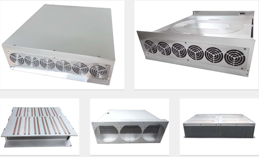
Which is why the shroud is a functional part, not cosmetic sheet metal. Its job is to leave the air nowhere to go except through the fins. Three consequences worth putting on the drawing:
- The gap between fin tips and duct wall is a dimension with a tolerance, not an assembly leftover.
- The transition from a round fan to a rectangular fin stack needs length to spread the flow. Bolting a round fan flat against a wide stack feeds the middle and starves the ends.
- The dead zone behind the fan hub is real. Fins directly under the hub see little flow, which is an argument for a short plenum, or for putting the highest heat somewhere other than dead centre.
Closing bypass is usually the cheapest thermal improvement available on an existing design — cheaper than more fins, and far cheaper than a bigger fan.
Inlet temperature is not ambient
An assembly is sized against the air arriving at it, and inside a cabinet that air has usually already passed over something else. In a sealed enclosure it recirculates and climbs further still.
Sizing against 25 °C when the real inlet sees 45 °C throws away most of the margin before a single part is made. If the inlet is unknown, measure it in the worst position on the existing machine, or tell us the cabinet layout and we will make a defensible assumption and write it on the drawing — so it stays visible instead of becoming a buried guess nobody can audit later.
Same logic on the filter. A filter is part of the impedance, and it only gets worse in service. Size the fan for the dirty end of the service interval, mark that assumption on the drawing, and it is much harder for the margin to be value-engineered away later by someone who never saw the reasoning.
Redundancy and noise, honestly
N+1 fans
Adding a redundant fan does not add its airflow. Fans in parallel share the same pressure, so the extra unit raises flow only modestly while adding cost and noise. What it buys is survival — when one fan stops, the module still cools well enough to keep running until the next service visit. On equipment where a thermal trip stops a production line, that is cheap. On a benchtop instrument that can simply be switched off, usually it is not. We build either and quote the honest airflow for both, rather than the flattering figure.
Noise
Noise rises steeply with fan speed, far faster than airflow does. So the reliable route to a quiet module is a larger, slower fan — which is a decision about the envelope taken early, not a fix applied late. Sharp edges in the flow path, fin tips sitting right at the hub, and tight finger-guard bar spacing all add tone on top of the broadband noise. If there is a noise limit in your specification, say so at enquiry: it changes fin pitch and envelope, not just a fan part number.
What we assemble into the module
| Element | Options | Chosen against |
|---|---|---|
| Fin block | Extruded, machined, or skived for high density | Fin ratio and quantity — see the process comparison |
| Spreading | Solid base, or embedded heat pipes | Whether heat has to travel across the base or just down through it |
| Base material | 6061 default, 6063 for the fins, copper under concentrated flux | Flux density and weight budget |
| Shroud & frame | Sheet aluminium or steel, machined mounting faces | Bypass control first, mounting second |
| Fans | Axial or blower, single or N+1, PWM or fixed | Static pressure at the operating point |
| Filter & guards | Washable or disposable media, finger guards | Site dust and the service interval you can keep |
| Structural alloy | 7075-T6 ≈130 W/m·K | Not used thermally — worse than 6061 and dearer |
| Stainless | 304 ≈16 W/m·K | Frames and fasteners only, never the thermal path |
What is in the catalogue — and where we come in
| What you need | In the catalogue? | What we do about it |
|---|---|---|
| Standard fan-sink for a standard package, standard bolt pattern | Yes — stocked by the thermal distributors | Buy it off the shelf — it will beat our price. Or ask us: if the catalogue part fits, we say so instead of quoting. |
| CPU tower cooler or a case fan kit | Yes — retail | Not our market. |
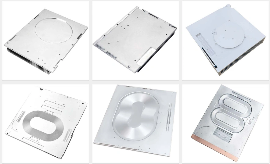
| Module that must fit an existing chassis opening | No — catalogue modules come in their own envelope | Shroud and frame built to your opening and mounting pattern |
| Fan row along one edge, device recessed into the base | No | Base machined for the device, fan row positioned to suit |
| Heat has to travel across the base before it reaches fins | No | Heat pipes embedded in the base under the fin stack |
| Obsolete cooling module a machine was built around | No — long discontinued | Measured from the old module and rebuilt, fans and all |
| Noise limit that the catalogue module misses | Fixed fan, fixed speed | Re-pitched fins and a larger slower fan in the same envelope |
| 50,000 modules a year of one fixed design | Effectively yes | A volume thermal house with its own tooling beats us. Go there. |
What we need to quote
- Heat load and where it sits on the base — a rough heat map beats a single wattage figure.
- Envelope, including the chassis opening the module has to fit and which way the air can enter and leave.
- Inlet air temperature — the real one, not room temperature.
- Allowed temperature rise, or the device case limit and we work back from it.
- Noise limit, if there is one. It changes fin pitch, not just the fan.
- Service reality — filter interval, whether a stopped fan is tolerable, whether anyone will ever clean it.
- Quantity now and per year.
No CAD needed. A sketch of the opening with the hot devices marked is a normal starting point, and we redraw it into CAD at no charge before anything is built.
A real job of this kind: A Special-Profile Heat Sink in 6061, Small Quantity — a special-profile 6061 heat sink in a small quantity, cut by wire EDM because an extrusion die would have cost more than the order.
Frequently Asked Questions
Because that rating is free-air delivery — what the fan moves when nothing is in front of it. Your fin stack is a restriction, and the denser the fins, the more it resists. The real operating point is where the fan's pressure-flow curve crosses your system's impedance curve, and on a dense sink a high-flow low-pressure fan can end up delivering a fraction of its headline number. This is why a smaller fan with a steeper pressure curve often outperforms a bigger one on paper. Send the fin geometry and the fan you intend to use and we will tell you roughly where the two curves meet before you build it.
Bypass is air that goes around your fin stack rather than through it. Air is lazy: presented with a dense fin field and a gap beside it, most of the flow takes the gap. A sink that measures well on a bench with a shroud can lose a large part of its performance in a chassis where the same fan blows past it. That is why the shroud is a functional part rather than cosmetic sheet metal, and why the clearance between fin tips and duct wall belongs on the drawing with a tolerance. Closing bypass is usually the cheapest thermal improvement available on an existing design — cheaper than more fins and much cheaper than a bigger fan.
A dirty one, always. A filter is part of the system impedance, and as it loads with dust that impedance rises, pushing the operating point back along the fan curve and reducing flow exactly when the equipment has been in service long enough to matter. Sizing on a clean filter produces a machine that passes acceptance and overheats a year later in a dusty plant. Tell us the service interval you can realistically expect on site and we will size against the dirty end of it, and say so on the drawing so nobody value-engineers the margin away later.
It depends on what a stopped fan costs you. Adding a redundant fan does not add its airflow, because fans in parallel share the same pressure and the extra unit mostly raises the flow a little while adding noise and cost. What it buys is survival: when one fan fails, the assembly still cools enough to keep running until the next service visit. On equipment where a thermal shutdown means a production line stops, that is cheap insurance. On a benchtop instrument that can be switched off, usually it is not. We build either, and we will give you the honest airflow figure for both cases rather than the flattering one.
Noise climbs steeply with fan speed — far faster than airflow does — so the reliable way to get a quiet assembly is a larger, slower fan rather than a small fast one, and that is a decision about the envelope taken early rather than a fix applied late. Sharp edges in the airflow path, fin tips sitting right at the fan hub, and finger guards with tight bar spacing all add tone on top of the broadband noise. If there is a noise limit in your specification, tell us at enquiry rather than at first article, because it changes the fin pitch and the envelope, not just the fan part number.
Not ambient, the inlet. Inside a cabinet the air arriving at your assembly has usually already passed over other equipment, so it can sit well above room temperature, and in a sealed enclosure it recirculates and climbs further. Sizing against 25 °C when the inlet sees 45 °C throws away most of the design margin before anything is built. If you do not know the real inlet, measure it in the worst-case position on the existing machine, or tell us the cabinet layout and we will make a defensible assumption and write it on the drawing so the number is visible rather than buried.
The whole module. Fin block machined, skived or extruded to suit, heat pipes embedded where the heat has to travel across the base, sheet metal shroud and mounting frame, fans, finger guards, filter and wiring loom, assembled and shipped as one part number. That is what most of the enquiries on this page are asking for, even when they arrive worded as a request for a heat sink. If you would rather buy the fin block and do your own assembly, that is fine too — we will still tell you what the shroud has to do.
Related: all fin processes compared · skived fin heat sinks · extruded heat sinks · heat pipe heat sinks · microchannel cold plates · fanless heat sink enclosures · front panels & rack ears
Get a Free Quote
Send the heat load, the chassis opening and — the one that decides everything — the real inlet air temperature. We reply within 12 hours.
// Fin density → fan type
Open fins
Axial, high flow
Forgiving case
Dense fins
High static pressure
Often a blower
- →We size against a dirty filter, not a clean one
- →Assumptions go on the drawing, not in someone's head
Response within 12h · Drawings kept confidential