What is actually happening inside the pipe
A heat pipe looks like a copper tube and behaves like nothing of the sort. It is sealed, evacuated, and holds a small charge of working fluid plus a wick lining the wall. At the hot end the fluid boils. The vapour rushes down the pipe to the cool end, gives up its latent heat and condenses. Then the liquid has to travel back to the hot end through the wick, and the cycle repeats.
Because latent heat carries so much more energy than conduction does, the effective conductivity of that loop runs one to two orders of magnitude above solid copper. This is why a 6.00 mm pipe can move heat that a copper bar of the same section could not.
But read the cycle again and the catch is obvious. Everything depends on the liquid getting back. The wick pumps it by capillary action, and gravity is either helping or resisting depending on which way the assembly is mounted. That single fact turns "which way up" from an installation note into a line on the specification.
The wick decides whether orientation matters
| Wick | How it pumps | Hot end below (gravity assists) | Hot end above (against gravity) | Pick it when |
|---|---|---|---|---|
| Sintered powder | Porous copper matrix, real capillary head | Full capacity | Still works, at reduced capacity | Orientation is unknown, variable, or inverted |
| Axially grooved | Grooves along the wall, low capillary head | Full capacity, lightest and cheapest | Loses most of its capacity | Orientation is fixed and gravity-assisted or horizontal |
| Mesh / screen | Woven layers, medium capillary head | Full capacity | Partial capability | A middle option, often on longer pipes |
The failure this table prevents: a grooved-wick assembly is specified, tested horizontally on a bench, passes, and ships. In the field the equipment gets rack-mounted the other way up, the wick can no longer lift the condensate, and the device runs hot at one customer site and not at the others. If the equipment can be installed more than one way — and most equipment can — specify sintered and pay for it.
Overload is a cliff, not a slope
Below its transport limit, a heat pipe holds the hot end within a few degrees of the cool end and behaves almost like a short circuit for heat. Push past that limit and the wick can no longer return liquid as fast as it is boiling away. The evaporator dries out, and its temperature runs away while the fins a few centimetres downstream still feel cool to the hand.
Two consequences worth designing around. First, the curve has a knee, not a slope, so margin is worth more here than on a solid heat sink where you simply run a little hotter. Second, any published capacity figure is only valid for the orientation, length and bend count it was measured at — quoting a pipe's Qmax without those three is quoting nothing at all.
Flattening and bending both cost you
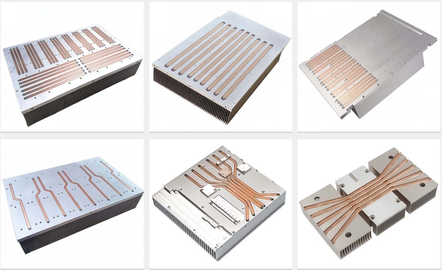
Pipes get flattened to fit thin envelopes and bent to reach around components. Both are normal, both are quantifiable, and neither is free.
- Flattening squeezes the vapour space and compresses the wick. A 6.00 mm round pipe pressed to 3.00 mm gives up a meaningful fraction of its capacity, and the loss steepens the flatter it goes. It is usually still the right trade — a flattened pipe that fits beats a round pipe that does not.
- Bending is gentler. Keep the radius at roughly three pipe diameters or more and count on each bend costing a little. A bend sitting right at the evaporator hurts more than one out along the condenser, because that is where the returning liquid is working hardest.
- Length works against the wick too: the further the liquid has to be pumped back, the lower the capacity, and the more the orientation question matters.
Send the envelope rather than a pipe count. We lay the pipes out to fit it and tell you what that layout costs in capacity, instead of quietly shipping an assembly that no longer meets your number.
How the pipe meets the metal
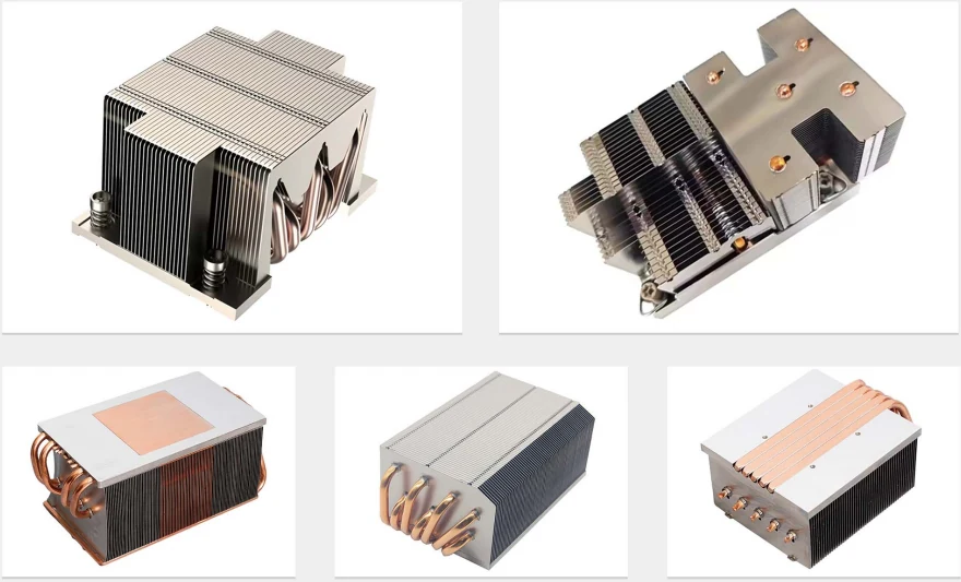
The pipe can be the best in the world and still be wasted at the joint. Three levels, and the cheapest is often good enough.
| Joint | What happens | Interface resistance | Use it when |
|---|---|---|---|
| Pressed into a milled groove | Pipe set into the groove with thermal filler closing the gap | Highest of the three | Moderate flux, cost-driven builds, larger areas |
| Soldered | Solder fills the groove all round the pipe | Low | The usual answer on anything power-dense |
| Direct-contact | Pipes machined flat on the mounting face and touching the device itself | Lowest — one interface removed | Concentrated sources, where a flat controlled clamp is available |
Which metals belong in the assembly
| Part | Material | Conductivity | Note |
|---|---|---|---|
| Heat pipe wall | Oxygen-free copper | ≈390 W/m·K | The pipe is always copper — the wick is sintered from the same metal |
| Base / spreader | Aluminium 6061 | ≈167 W/m·K | Default. Takes threads, machines cleanly, anodises |
| Fin stack | Aluminium 6063 | ≈201 W/m·K | Better conductor than 6061 and the standard fin alloy |
| Base, high flux | Copper C11000 | ≈388 W/m·K | When the spreading path under the device is the bottleneck |
| Base, structural | Aluminium 7075-T6 | ≈130 W/m·K | No thermal case — worse than 6061 and dearer. Strength alloy in the wrong job. |
| Anything | Stainless 304 | ≈16 W/m·K | About ten times worse than 6061. Not a heat sink metal. |
One question this raises and most pages dodge: copper pipes in aluminium fins — is that a galvanic pair? In a dry, air-cooled assembly, no. Galvanic corrosion needs an electrolyte bridging the two metals, and a sealed enclosure or a normal ventilated cabinet has none. It becomes real in condensing environments, marine air, or wash-down duty, and there the answer is a conformal coating, nickel on the copper, or an all-copper build. That is a different question from a liquid loop, where an aluminium plate in a copper circuit does corrode from the inside — see the cold plate page for that case.
What is in the catalogue — and where we come in
| What you need | In the catalogue? | What we do about it |
|---|---|---|
| Standard tower cooler for a standard CPU socket | Yes — a whole retail industry | Buy it off the shelf — retail pricing beats us. Or ask us: if the retail cooler fits, we say so instead of quoting. |
| Catalogue heat pipe sink that fits, in the orientation you will use | Yes, if it fits | Buy it. We will tell you when that is the case. |
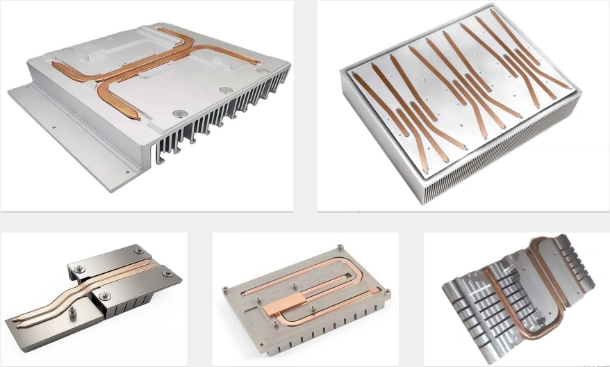
| Pipes routed around a connector, a capacitor bank or a mounting boss | No — catalogue layouts are fixed | Pipes laid out to your board, bent and flattened to your envelope |
| Two hot spots, one fin stack | Rare | Branched pipe sets from separate evaporators into a shared condenser |
| Fins have to sit somewhere the device cannot | No | Pipes bridging separate blocks — remote fin stack |
| Equipment can be mounted either way up | Catalogue data is usually horizontal only | Sintered wick specified deliberately, and we say what it costs |
| Envelope too thin for round pipes | No | Flattened pipes, with the capacity penalty stated up front |
| 10,000 units a year of one fixed design | Effectively yes | A dedicated thermal house with its own pipe line will beat us. Go there. |
And the honest one that costs us work: "Do I even need heat pipes?" Often not. If the device and the fins can sit close together and there is room for surface area, a plain skived or extruded sink does the job for less money and with nothing inside it to dry out. Pipes earn their cost when heat has to travel — around an obstruction, out to a remote fin stack, or spread across a base far larger than the device. We will say which case you are in before quoting the more expensive thing.
What we need to quote
- Power to move and the allowed temperature rise — or just the device and its case temperature limit, and we work it out.
- The envelope the assembly has to live in, and where the hot spot sits inside it.
- Mounting attitude, including whether the equipment can be installed more than one way up. This is the one everybody forgets.
- Airflow — a fan curve, or "still air" if there is none.
- Quantity now and per year.
No CAD required. A dimensioned sketch of the space with the hot spot marked is a normal starting point, and we redraw it into CAD at no charge before anything is built.
A real job of this kind: A Special-Profile Heat Sink in 6061, Small Quantity — a special-profile 6061 heat sink in a small quantity, cut by wire EDM because an extrusion die would have cost more than the order.
Frequently Asked Questions
Because a heat pipe has a direction and a solid metal heat sink does not. Inside the sealed pipe, working fluid evaporates at the hot end, travels to the cool end as vapour, condenses there, and then has to get back to the hot end through the wick. That return trip is the whole ball game. If the hot end sits below the cool end, gravity helps the liquid return and the pipe performs at its best. If the hot end sits above, the wick has to pump the liquid upwards against gravity, and how well it manages that depends on which wick is inside. Nobody can size the pipe without knowing the attitude, so we ask rather than assume horizontal and hope.
Sintered powder if the orientation is unknown, variable, or against gravity. The sintered structure is a porous copper matrix with real capillary pumping, so it keeps working with the evaporator above the condenser, at reduced capacity. Axially grooved pipes are lighter, cheaper and excellent horizontally or gravity-assisted, but the grooves have far less capillary head and lose most of their capacity when asked to lift liquid. Mesh sits between the two. If the equipment can be installed either way up in the field — and it usually can — specify sintered and accept the cost, because the alternative is a heat sink that passes on the bench and fails at a customer site.
It does not degrade gracefully, which is what makes this worth designing for. Below its transport limit a heat pipe holds the evaporator close to the condenser temperature. Past that limit the wick can no longer return liquid as fast as it is boiling off, the evaporator dries out, and its temperature runs away while the rest of the assembly still looks cool. On a test bench this shows as a sudden knee in the curve, not a slope. Design with margin, and treat the published capacity of any pipe as valid only for the orientation, length and bend count it was quoted at.
Yes, and both cost capacity, so it is worth knowing the price. Flattening reduces the vapour space and squeezes the wick, so a 6.00 mm round pipe pressed to 3.00 mm gives up a significant fraction of its capacity — the flatter it goes, the steeper the loss. Bending is gentler but not free: keep the radius at about three pipe diameters or more, and count on each bend costing a little. A bend right at the evaporator hurts more than one out along the condenser. Send the envelope and we will lay the pipes out for it and tell you what the layout costs you, rather than quietly delivering a pipe that no longer meets your number.
It matters, and there are three levels. Pressed: the pipe is set into a milled groove with thermal filler, which is the cheapest and adds an interface. Soldered: solder fills the groove around the pipe, which removes most of that interface at a higher cost and is the usual choice on anything power-dense. Direct-contact: the pipes are machined flat on the mounting face so they touch the device itself with no base metal between, removing an interface, which suits concentrated sources but needs a flat, controlled clamp. Which one to use follows from your flux and your budget, and we will say plainly when the cheap joint is good enough.
Not in a dry air-cooled assembly, which is what this is. Galvanic corrosion needs an electrolyte bridging the two metals, and inside a sealed enclosure or a normal ventilated cabinet there is none. It becomes a real question in condensing environments, marine air, or anywhere the unit is washed down — and there the answer is a conformal coating, nickel plating on the copper, or an all-copper build. That is a different conversation from a liquid loop, where an aluminium plate in a copper circuit does corrode from the inside; see the cold plate page for that case.
Five things. The power to move and the allowed temperature rise, or the device and its case temperature limit if you would rather we work it out. The envelope the assembly has to live in. The mounting attitude, including whether the equipment can be installed more than one way. Airflow, if any — fan curve or just still air. And quantity. No CAD needed: a dimensioned sketch of the space and the hot spot is enough to start, and we redraw it into CAD at no charge. If a plain machined or skived heat sink would do the job without pipes, we say so before quoting the more expensive thing.
Related: all fin processes compared · skived fin heat sinks · extruded heat sinks · liquid cold plates · machined aluminum heat sinks · copper machining · order from a sketch
Get a Free Quote
Send the power, the envelope and — this is the one people forget — which way up it gets mounted. We reply within 12 hours.
// Wick by orientation
Fixed & assisted
Grooved
Lighter, cheaper
Unknown or inverted
Sintered
Works against gravity
- →We say when you don't need pipes at all
- →No CAD? A sketch of the space and the hot spot is enough
Response within 12h · Drawings kept confidential