Two routes, and the one nobody offers you
Ask ten extrusion suppliers for a custom heat sink and ten of them quote a die. It is not dishonest — it is just the only product they sell. But a die is a one-time cost that has to be carried by every piece you will ever order from it, so at fifty or a hundred pieces it swamps everything else on the quotation.
The second route: start from a stock 6063 profile whose fin section is already close to what you need, then machine the rest. Cut to your length, face the base, add the mounting pattern, counterbores, tapped holes, and any cut-outs where a connector or a capacitor has to pass through. You end up with a part in your dimensions, built on a section somebody else already paid to develop, with no die and no minimum.
| Your situation | Route | Why |
|---|---|---|
| 1 – 100 pieces, a stock section is close | Stock profile, machined | No die to carry. Your footprint comes from the machining, not the section. |
| 1 – 100 pieces, nothing close exists | Machined or skived fin field | Cutting the fins outright still beats a die at this volume |
| 100 – 500, stock section close enough | Stock profile, machined | Usually still ahead, and it keeps the option open |
| 500+, section is yours | New die | Die amortises; piece price drops below every other route |
| Any volume, fins under 1.00 mm | Not extrusion at all | Below the physical floor — see skived fin |
| Any volume, fin heights must vary | Not extrusion at all | A die makes one constant section, full stop |
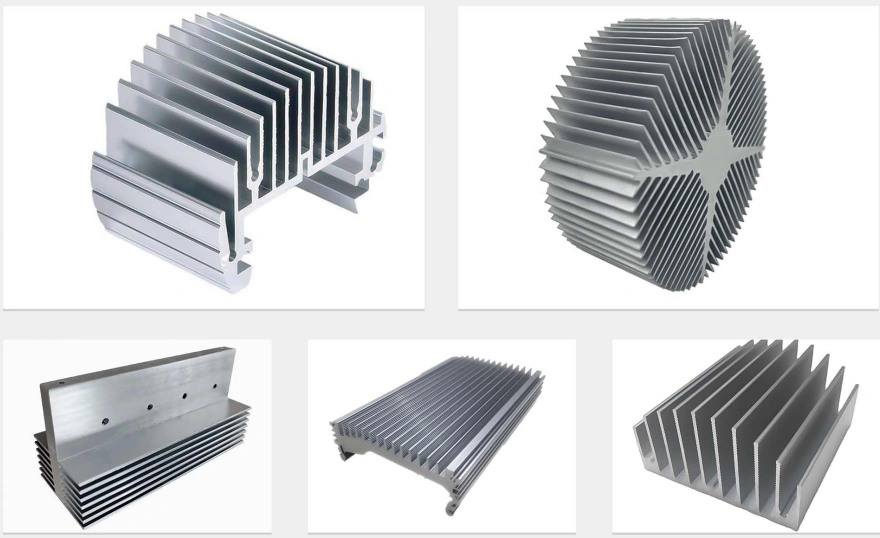
What the die physically limits
Hot aluminium is pushed through a slot in a steel die and pulled out the other side. Everything extrusion can and cannot do comes from that sentence.
| Limit | Typical value | Consequence |
|---|---|---|
| Minimum fin wall | ≈1.20 mm in 6063 | Thin slots in the die run cold, wear fast, produce wavy fins |
| Fin aspect ratio | ≈12:1 | A 1.20 mm fin reaches roughly 14.00 mm tall |
| Draft angle | 1 – 2° per side | Parallel-sided fins cannot be extruded as drawn |
| Cross-section | One, constant | No stepped heights, no gaps for screws, no two-sided fins |
| Root radius | ≈0.50 mm | Sharp internal corners crack the die — they get a radius whether the drawing shows one or not |
| Length tolerance | Loose as extruded | If the length matters it gets sawn and faced afterwards, not extruded to size |
Which aluminium, and why 6063 nearly always wins
| Alloy | Conductivity | Extrudes? | Use it when |
|---|---|---|---|
| 6063 | ≈201 W/m·K | Yes — the standard | Almost every heat sink. Fine detail, clean anodising. |
| 6061-T6 | ≈167 W/m·K | Yes, less freely | Only when the sink also carries load or stressed threads. Costs ~17% conductivity. |
| 1050 | ≈229 W/m·K | Yes | Best conductivity of the four — but too soft to hold a mounting thread |
| 7075-T6 | ≈130 W/m·K | Not into fin profiles | Never for thermal reasons. Strength alloy in the wrong job. |
| Copper C11000 | ≈388 W/m·K | No — not extruded into fins | Copper fin density comes from skiving, not a die |
| Stainless 304 | ≈16 W/m·K | No | Twelve times worse than 6063. Not a heat sink metal. |
One more thing about finish, since it comes up on every extrusion quote. Black anodising does help — less than people expect. The gain is radiative, so it counts in still air and becomes close to irrelevant the moment a fan is moving air across the fins. In natural convection, specify it. In forced convection, specify it for appearance and corrosion resistance and do not budget any thermal margin against it.
What is in the catalogue — and where we come in
| What you need | In the catalogue? | What we do about it |
|---|---|---|
| Standard profile in a standard length, standard holes | Yes — heat sink makers and electronics distributors stock it deep | Buy it off the shelf — it will be cheaper than anything we quote. Or ask us: if the catalogue part fits, we say so instead of quoting. |
| Right profile, wrong length, wrong hole pattern | Half — the section exists, your part does not | We buy the section and machine your part out of it. MOQ 1, no die. |
| Profile discontinued, machine still in service | No | We measure the old part and rebuild it, machined or from a new die depending on quantity |
| New section, 2,000 pieces a year | No | New die, quoted against your section, then production runs off it |
| Fins under 1.00 mm, or ratios past 12:1 | No — physically outside extrusion | Cut instead: skived or bonded fin |
| Fin field that steps in height or opens for screws | No — one constant section | Machined or skived fin field to your layout |
| 50,000 pieces a year of one standard section | Effectively yes | A dedicated extrusion house with its own press will beat us. Go there. |
The message that starts most of these jobs: "The catalogue profile is right except it is 40 mm too long and the mounting holes are in the wrong place." That job needs no die, no minimum and no tooling conversation — it needs a saw, a mill and somebody willing to take an order for eight pieces.
What we need to quote
- The profile, if one already exists — a part number, a photo with a scale, or the part itself. We can work from any of the three.
- Base footprint and overall length, plus where the mounting holes and cut-outs go.
- Fin thickness, height and pitch if the section is new — these decide immediately whether extrusion is even the right process.
- Quantity now, and quantity per year. This is the number that picks the route, and getting it roughly right matters more than any other line on the enquiry.
- Finish — mill, clear anodised, black anodised, or chromate where a face must stay conductive.
No CAD is fine. A dimensioned sketch, or the old heat sink in a box, is a normal starting point here — we redraw it into CAD at no charge before anything is cut, and you keep the drawing.
A real job of this kind: A Special-Profile Heat Sink in 6061, Small Quantity — a special-profile 6061 heat sink in a small quantity, cut by wire EDM because an extrusion die would have cost more than the order.
Frequently Asked Questions
Usually not, and this is where most money gets wasted. A die is a one-time cost that has to be spread over every piece you will ever order from it, so at 50 or 100 pieces it dominates the price. The alternative almost nobody offers you: take a stock 6063 profile whose fin section is close enough, cut it to your length, and machine everything else — mounting pattern, pockets, counterbores, tapped holes, cut-outs at the ends. You get your footprint without owning a die, from 1 piece. A die starts to pay when the volume is there and no stock section is close, and we will say which case you are in before you spend anything.
About 1.20 mm is the normal floor in 6063, and the fin aspect ratio lands near 12:1 — so a 1.20 mm fin runs to roughly 14.00 mm tall. Specialised high-ratio presses push further, at a price. The reason for the limit is that molten-soft aluminium has to be pushed through a narrow slot in the die and then survive being pulled out; thin, deep slots run cold, wear fast and produce fins that wave. If your design needs 0.30 or 0.50 mm fins, extrusion is the wrong process and no supplier can fix that with a better die — that geometry belongs to skiving or bonded fin.
Because the profile has to come out of the die and off the press without binding, so each fin carries draft, typically one to two degrees per side. The fin is therefore always thicker at the root than at the tip. That happens to suit the physics — the root carries the whole heat flow of the fin while the tip carries almost none — but it is a manufacturing requirement first. It also means a drawing calling for parallel-sided fins cannot be extruded as drawn, whatever the thickness.
6063 for nearly every heat sink. It extrudes freely, holds fine detail in the die, takes a clean anodised finish and conducts about 201 W/m·K. 6061-T6 is the structural choice — stronger, but it extrudes less freely, needs thicker walls, and conducts about 167 W/m·K, roughly 17 percent less. Pick 6061 only when the heat sink is also carrying load or being threaded and stressed. 7075-T6 at about 130 W/m·K has no thermal case at all and is not extruded into fin profiles. Aluminium 1050 conducts best of the four at about 229 W/m·K but is too soft to hold a mounting thread.
That is the single most common heat sink job here and it needs no die at all. We take the stock section, cut it to your length, face the base flat, add the mounting pattern, counterbores and tapped holes, machine any cut-outs where a connector or capacitor has to pass, and finish it. The result is a part in your dimensions built on a section somebody else already paid to develop. If the old profile has been discontinued and you only have the part in your hand, we measure it and reproduce it — including rebuilding the extrusion-look section as a machined part when quantities are low.
Four things, all following from one fact: a die produces exactly one cross-section, constant along the whole length. So it cannot give you fin fields that step between heights on one base; it cannot open a gap in the field so a mounting screw passes through; it cannot put fins on both faces of one base; and it cannot make a wave or corrugated fin, since the section would have to change along the length. Every one of those is routine on a cut fin field, which is why the two processes end up complementary rather than competing.
Yes — clear, black or coloured anodising, and black does help slightly, but less than most people expect. The gain is in radiation, which matters in still air and becomes almost irrelevant once a fan is moving air across the fins. In natural convection black anodising is worth having; in forced convection specify it for appearance and corrosion, not for thermal performance. If any face has to stay electrically conductive, chromate conversion coating keeps conductivity where anodising does not.
Related: all fin processes compared · skived fin heat sinks · machined aluminum heat sinks · LED heat sinks · heat sink enclosures · obsolete profiles remade · order from a sketch
Get a Free Quote
Send the profile (part number, photo or the part itself), your length, hole pattern and quantity. We reply within 12 hours and say plainly whether a die is worth it.
// Die or no die
1–100
Stock + machining
No die cost at all
100–500
Usually still stock
Keeps options open
500+
New die
Section becomes yours
- →Discontinued profile? We rebuild it from the old part
- →We say when the catalogue is cheaper — before you pay us
Response within 12h · Drawings kept confidential