The one number that decides the process: aspect ratio
Take the fin height on your drawing and divide it by the fin thickness. That ratio, not the material and not the quantity, is what rules processes in or out.
The reason is where the cutting force lands. In milling the fin is what is left over after the metal beside it is removed, so the finished fin has to stand there and take the cutter. A 0.40 mm wall 9.00 mm tall will chatter, lean and tear long before the cut finishes — which is why milled fins run out of road somewhere around 8:1. In skiving the fin is the material that was removed: a blade peels a thin layer off the solid block and folds it upright, still attached at the root, so no tool ever touches the finished fin. In bonded fin the fin was never cut at all — it is separately rolled sheet, slotted into a machined base and soldered.
Same shape on the drawing. Three different sets of limits.
| Process | Fin thickness | Aspect ratio | Metals it works in | Tooling | Sensible quantity |
|---|---|---|---|---|---|
| CNC milled fin | from ~1.00 mm | to ~8:1 | Any machinable metal | None | 1 – 500 |
| Skived fin | 0.20 – 1.00 mm | to ~40:1 | C11000, C10200, 1050, 6063 only | Blade + fixture per pitch | 50 – 50,000 |
| Bonded fin | 0.30 – 1.00 mm sheet | past 50:1 | Any solderable pairing, incl. copper fins on aluminium base | None | 1 – 2,000 |
| Extruded profile | from ~1.20 mm | to ~12:1 | 6063 and other soft extrusion alloys | Extrusion die | 500+ |
| Folded / zipper fin | 0.15 – 0.50 mm strip | high | Aluminium and copper strip | Forming tool | 1,000+ |
| Stamped fin | 0.30 – 1.50 mm sheet | low | Aluminium and copper sheet | Progressive die | 10,000+ |
| Heat pipe assembly | n/a — pipe Ø3 – 8 mm | n/a | Copper pipe into aluminium or copper fin stack | Partial | 100+ |
| Microchannel cold plate | channel under 1.00 mm | n/a | Aluminium and copper | Brazing fixture | 50+ |
Read the table from your own part: fin ratio under 8:1 and quantity under 500 → machined, and you pay no tooling at all. Ratio past 12:1 → skiving or bonded fin, and which one depends on how many you need.
One consequence of that table is worth pulling out, because it sits on a dimension buyers treat as free: the base thickness is set by the process, not by you. A skiving blade travels along the block and its reaction runs into the metal underneath, so a skived part needs a base stiff enough to stay flat while the fin field is being cut — go too thin and it bows, and the fin heights drift with it. Milling loads the base locally and the fixture takes most of that, so a milled fin field will sit on a thinner base than a skived one of the same footprint. If your drawing carries both a thin base and a fin ratio only skiving can reach, those two lines contradict each other, and one of them has to give before anyone can quote it.
Which metal survives which process
This list surprises people, because the alloys that are easiest to machine are exactly the ones that cannot be skived. Free-machining grades get their behaviour from additives — tellurium in copper, lead in brass — whose whole job is to break the chip into short pieces. Skiving needs the opposite: one continuous ribbon that survives being folded through 90°.
| Metal | Conductivity | Density | Can be skived? | Note |
|---|---|---|---|---|
| Copper C11000 (Cu-ETP) | ≈388 W/m·K | 8.96 g/cm³ | Yes — the reference | Ductile, folds without cracking |
| Copper C10200 (OFC) | ≈390 W/m·K | 8.94 g/cm³ | Yes | Used where oxygen content matters |
| Aluminium 1050 | ≈229 W/m·K | 2.70 g/cm³ | Yes | Soft, best aluminium for skiving |
| Aluminium 6063 | ≈201 W/m·K | 2.70 g/cm³ | Yes | Also the standard extrusion alloy |
| Copper C14500 (tellurium) | ≈355 W/m·K | 8.94 g/cm³ | No | Tellurium breaks the chip — machines beautifully, folds badly |
| Brass CuZn39Pb3 | ≈117 W/m·K | 8.47 g/cm³ | No | Copper's weight with worse conductivity than aluminium |
| Aluminium 6061-T6 | ≈167 W/m·K | 2.70 g/cm³ | No — too hard in temper | Fine for milled fins and enclosures |
| Aluminium 7075-T6 | ≈130 W/m·K | 2.81 g/cm³ | No | Strong, but thermally a step backwards from 6061 |
| Stainless 304 | ≈16 W/m·K | 7.93 g/cm³ | No | Ruled out on conductivity before process even matters |
Two conclusions people rarely see written down. Brass has no place in a heat sink — it carries copper's mass at less than a third of copper's conductivity, which is worse than aluminium on both counts at once. And if your drawing calls for 6061-T6 with 0.50 mm fins, the drawing contradicts itself: that alloy in that temper will not skive, so either the fin gets thicker or the base gets a bonded fin.
What the fin field can do that a die cannot
An extruded profile has one constant cross-section down its whole length. Every fin the same height, the field running edge to edge, no interruptions. That is exactly why extrusion is cheap — and exactly where it stops.
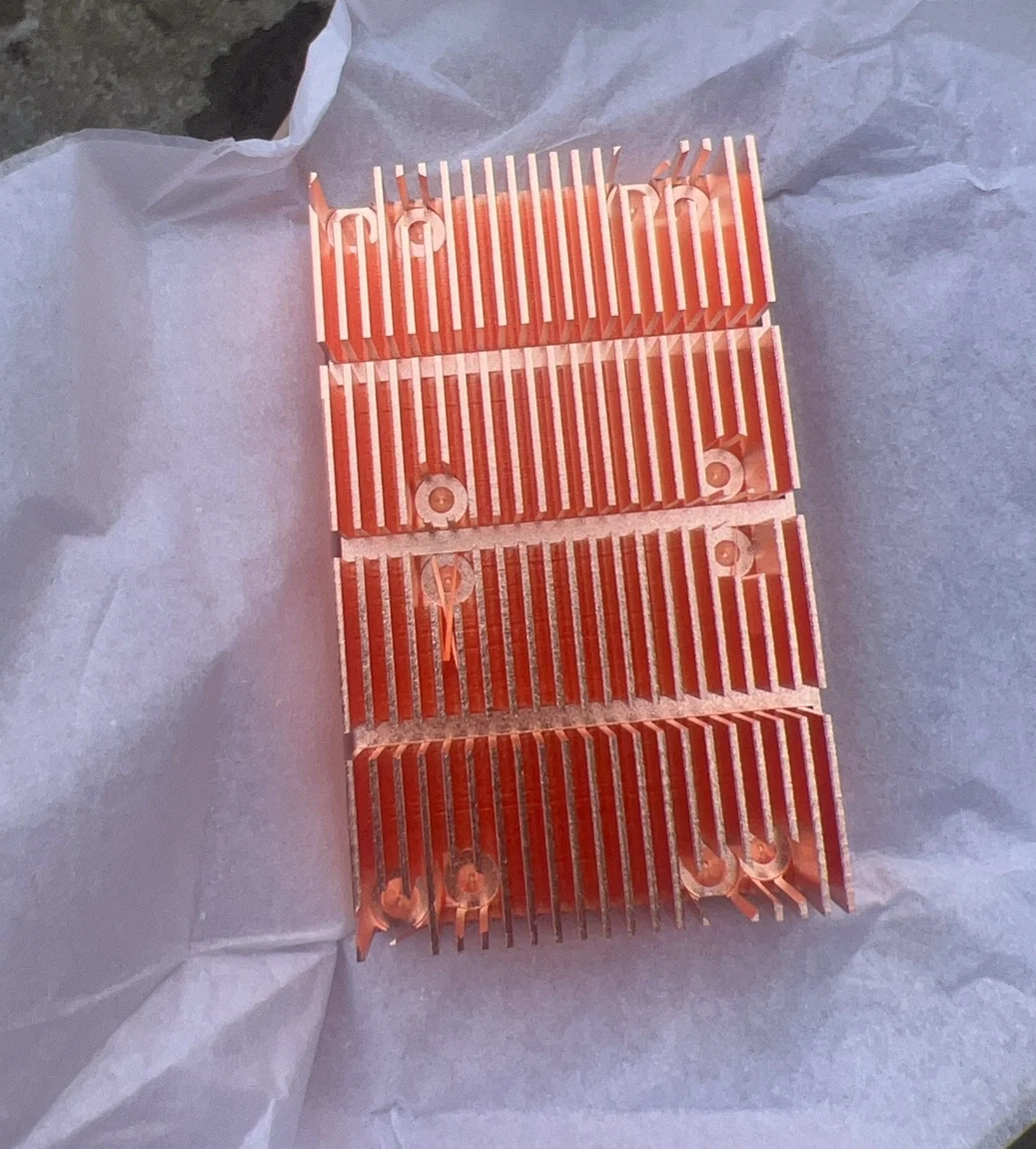
That part shows the feature a catalogue profile cannot give you: the fin field stops where it needs to stop. Screws pass through it, pads sit inside it, heights step across it. On a sealed box the base under the fin field is the case wall itself, which is how a battery management enclosure gets heat out when the box cannot be vented. Two-sided fins — a field on both faces of one base — are the other case a single die cannot produce, and the same is true of wave or corrugated fins, where the fin is deliberately not flat so the boundary layer keeps breaking up. More parts, and the geometry limits behind them, on the skived fin page.
Quantity decides the route, not the drawing
The same geometry gets built three different ways depending only on how many you order. This is the part most suppliers will not spell out, because two of the three answers make them less money.
| Quantity | Route we propose | Why | What you give up |
|---|---|---|---|
| 1 – 50 | Bonded fin on a machined base | No blade, no fixture, no die to amortise | A joint at the fin root — a little contact resistance |
| 50 – 500 | Skiving or bonded fin, decided on the part | Blade cost starts to spread; thin copper favours skiving | Lead time for blade grinding if skived |
| 500 – 5,000 | Skiving, or extrusion if the section allows it | Monolithic fin root, no joint anywhere in the heat path | Fin pitch locked to the blade set |
| 5,000+ | Extrusion, or stamping through our partner press shop | Die amortises; piece price drops well below any machined route | The die — its cost up front and its lead time before first parts |
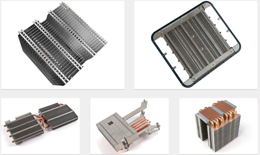
The opposite end of that table has a worked example too: a 200 mm special profile in 6061 wanted in a small quantity, where the extrusion die would have cost more than the whole order. The section goes through the block on a wire instead — wire EDM instead of an extrusion die.
What is in the catalogue — and where we come in
Most heat sink problems are not our problem to solve, and saying so saves everyone a week.
| What you need | In the catalogue? | What we do about it |
|---|---|---|
| Standard extruded profile, standard footprint, off-the-shelf sizes | Yes — heat sink makers and electronics distributors stock it deep | Buy it off the shelf — it will be cheaper than anything we quote. Or ask us: if the catalogue part fits, we say so instead of quoting. |
| PC and gaming cooler, CPU tower, RAM cooler | Yes — a whole retail industry | Not our market. Retail coolers have their own makers and their own prices. |
| Catalogue profile that is right except it is 12 mm too long | Half — the profile exists, your length does not | We machine the profile down, add your mounting pattern and pockets |
| Fin field that must step in height, or open up around screws | No — one die, one constant section | Skived or milled fin field cut to your layout, see the parts above |
| 0.30 mm copper fins, and you need 20 pieces | No — skiving shops quote 500 minimum | Bonded fin: same density, no tooling, from 1 piece |
| Obsolete heat sink a machine was designed around, no drawing left | No — the profile was discontinued | We measure the old part and rebuild it, including the extrusion look |
| Two-sided fins, or wave fins for a duct | No — a die cannot make either | Cut both faces, or form the wave, on a machined base |
| Stamped fin, 50,000 pieces a year | No — needs a progressive die cut for your section | We quote it through our partner press shop: die and piece price together, from your drawing and annual volume |
The sentence we hear most often, almost word for word: "I need 20 pieces with 0.4 mm fins and every skiving shop I contact wants a 500-piece minimum." That minimum is about the blade and the fixture, not about your fin. Bonded fin gets you the same fin density at quantity 1, and we will tell you the crossover point where switching to real skiving starts to pay.
The seven routes we build
Skived fin
Fins from 0.20 mm lifted out of the base itself, aspect ratios past 40:1, in C11000 copper or 1050 / 6063 aluminium. Segmented fields, stepped heights, two-sided and wave fins included.
Extruded profile
6063 profiles cut, machined and finished to your footprint — or a new die when the volume justifies one. The cheap answer whenever a constant section fits.
Machined fin & enclosure
Milled fins under 8:1 with pockets, bosses and cavities in one part. No tooling, MOQ 1. Also the route for an integrated heat sink enclosure.
Heat pipe assembly
When the heat has to travel — around an obstruction or out to a remote fin stack. Copper pipes pressed, soldered or machined flat into the base. Mounting attitude is a specification here, not an installation detail.
Microchannel cold plate
When air has run out and the flux is concentrated. Sub-millimetre passages buy heat transfer no fin matches — and catch every particle the loop produces, which is why the circuit matters more than the plate.
Fan-cooled assembly
The whole module, not the bare fin block — shroud, fans and filter included. Fans get chosen on static pressure at the operating point, and the shroud exists to stop air escaping around the fins.
Liquid cold plate
When air has run out: machined channels, pressed copper tube, or microchannel plates for concentrated flux. Paired with custom loop fittings.
What your drawing is probably missing
Four things go missing on heat sink drawings more often than anything else, and every one of them changes the price.
- The specific alloy — not "copper" or "aluminium". C11000 and C14500 are both copper and they behave nothing alike.
- Flatness of the contact face. On a thermal interface this is the dimension that sets the price. A plate that rocks throws away performance no fin design can win back.
- Roughness of that same face.
- The finish. Nickel plating adds a layer far less conductive than copper — on the contact face, specify it as thin as possible or mask it off. Copper cannot be anodised at all; that is passivation or nickel.
If one of the four is missing we ask before quoting rather than assuming a value and pricing the wrong part. Send a STEP file, a dimensioned drawing, a hand sketch or the old part itself — all four are normal starting points here, and we redraw a sketch into CAD before machining at no charge.
If the drawing names the alloy in another system — EN AW-6063 / AlMg0.7Si, A6061, LD31 — the aluminium alloy equivalents chart shows which alloy it is and what the fin material becomes.
Frequently Asked Questions
Work it from the fin, not from the process name. Divide fin height by fin thickness — that ratio decides almost everything. Below about 8:1 a milled fin is fine and needs no tooling at all. Between 8:1 and roughly 12:1 an extrusion die is the cheap answer once quantity justifies it. Past 12:1 you are into skiving or bonded fin, because the fin can no longer stand against a cutter or survive being pushed through a die. Then check the metal: if the drawing says 6061-T6, 7075-T6 or brass, skiving is off the table whatever the ratio says.
Because of where the cutting force lands. In milling the fin is what remains after the metal beside it is removed, so the finished fin has to stand up to the cutter — a 0.30 mm wall 9.00 mm tall chatters and folds over. In skiving the fin is the removed metal: a blade lifts a thin layer off the block and folds it up, so no tool ever acts on the finished fin. A bonded fin avoids the problem a third way — the fin is separate rolled sheet that was never cut at all, only slotted into the base.
That minimum is about tooling, not about the fin. Skiving needs a dedicated blade and fixture ground to your fin pitch, and extrusion needs a die; neither cost spreads across 20 pieces. The way out is bonded fin: 0.30 to 1.00 mm rolled sheet set into slots machined in the base and soldered or brazed. It reaches the same fin density with no tooling, and the honest difference is a joint at the fin root that adds a little contact resistance. We will also tell you the quantity at which switching to real skiving starts to pay.
Copper C11000 conducts about 388 W/m·K against roughly 201 W/m·K for aluminium 6063 — 1.9 times the conductivity for 3.3 times the mass, since copper sits at 8.96 g/cm³ against 2.70. Copper's advantage is concentrated in the base, directly under the hot spot, where heat has to spread sideways. The fins themselves are limited by air, not by metal, so extra aluminium surface often beats the same volume of copper. If the unit hangs off a mast, flies, or pays for weight in a rack, aluminium usually wins. If the flux is concentrated and there is no room for more surface, copper wins. A copper base carrying aluminium fins is the middle option and we build it.
Yes — through a qualified partner press shop that owns the press line. The economics do not change, though. A progressive die only pays for itself spread across tens of thousands of pieces, so below roughly 10,000 a year a skived or bonded fin usually lands cheaper once the die cost is counted into the total. Send the drawing with your annual volume and we quote the die and the piece price together; where the numbers say the machined route wins, we will say so.
Yes, and this is where a catalogue extrusion usually fails. An extruded profile has one constant section along its whole length, so every fin is the same height and the field runs edge to edge. We cut fin fields that step between heights across one base, that open a clearance notch so a mounting screw or a connector can pass through the field, and that stop short of a machined pad. Two-sided fins — a fin field on both faces of the same base — are the other case a single die cannot produce.
Four things go missing more often than any others on heat sink drawings. The specific alloy, not just copper or aluminium, because C11000 and C14500 behave nothing alike. The flatness of the contact face, which on a thermal interface is the dimension that sets the price. The roughness of that same face. And the finish, remembering that nickel plating adds a layer far less conductive than copper, so on the contact face it should be specified as thin as possible or masked off. If one is missing we ask before quoting instead of assuming.
Related: skived fin heat sinks · extruded heat sinks · machined aluminum heat sinks · LED heat sinks · cold plates · liquid cooling manifolds · cooling plate case study · copper machining · order from a sketch
Get a Free Quote
Send the footprint, fin height and thickness, the component you are cooling and the quantity — or just a drawing. We reply within 12 hours.
// Route by quantity
1–50
Bonded fin
No tooling at all
50–500
Either route
Decided on the part
500+
Skived
Monolithic fin root
- →No CAD? A sketch with fin pitch and height is enough
- →We say when the catalogue is cheaper — before you pay us
Response within 12h · Drawings kept confidential