EKINSUN is a manufacturer, and this is the page we send before a worn part is shipped to us. Get the reading off the right face and one caliper is enough; get it off the worn face and a CMM will only measure the damage with more decimal places.
Where the wear sits, and what to measure instead
Every row below is the same argument applied to a different part: the surface that carried the load is the surface that changed, so the design dimension has to come from somewhere else. The last column is what we fall back on when the part has no unworn surface left at all.
| Part | Where the wear concentrates | Measure this instead | Never measure | Fallback source |
|---|---|---|---|---|
| Spur or helical gear | Tooth flank near the pitch line, where rolling turns into sliding | Tip circle diameter plus a tooth count: m = OD ÷ (z + 2) | Tooth thickness at the pitch line | Mating gear and centre distance fix the module independently — see replacing a discontinued gear |
| Shaft (bearing and seal seats) | Seal running track, which cuts a groove; bearing seats fretted | An unloaded length of the same diameter step, next to the shoulder | The bottom of the seal groove | The bearing number gives the journal back: a 6205 seats on Ø25 |
| Plain bushing | One side of the bore, in the load direction — it goes oval, not undersize | Outside diameter and length, the press-fit face that never slid | The bore in its widest direction | DIN 1850 and ISO 3547 sizes are catalogue stock and cheaper bought than turned — check first |
| Pump wear ring | The running clearance, on the ring and on the impeller at the same time | Casing bore and impeller hub — the two mating parts | The worn face of the ring itself | Ring and impeller are reproduced as a pair; a new impeller against an old ring still leaks internally |
| Needle plate / punched plate | The needle hole, belled out into a funnel | Plate outline, mounting holes, thickness | The hole diameter, at any depth | Needle size sets the hole, not the worn plate — see needle plates |
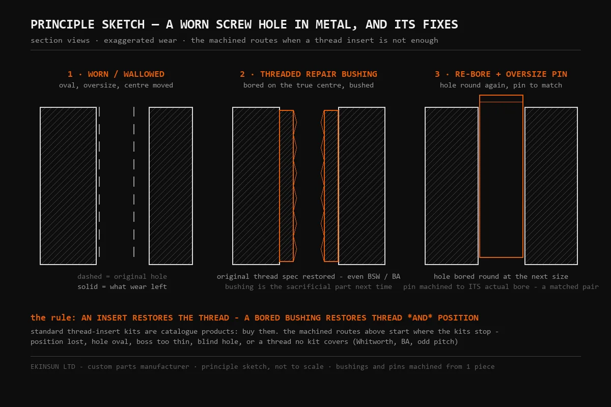
| Tapped hole in a housing | Thread flanks, pulled and stripped at the first engaged threads | Hole spacing, boss height, counterbore, and the pitch on an unworn thread further down | Flank-to-flank on the stripped threads | Pitch comes from the standard series once the diameter is known — see worn screw holes |
| Valve seat / sealing cone | The sealing band, pitted and grooved | Press-fit outside diameter and overall height | The cone angle on the worn band | Standard seat angles, confirmed against the valve disc that runs on it |
| Linear way / slide | The middle of the travel, where the carriage spends its life | The last 20–30 mm at each end, which the carriage rarely reaches | Anywhere in the working stroke | The rail section is a standard profile; only length and hole pattern are yours |
| Nozzle / orifice | The outlet bore, eroded open by flow | Mounting thread, body form, overall length | The outlet diameter | The rated flow gives the original orifice back, not the caliper |
Measured the worn part and want a new one? EKINSUN is a custom parts manufacturer: we make the new part from your measurements or from the sample itself to your drawing, sketch or sample — the original material or a better one — from 1 piece, quoted in 12 hours and shipped duties paid. Standard sizes can often be supplied from stock; the more pieces, the lower the unit price. Reverse engineering from a sample →
Is the reading you already took usable?
If the part is already measured and on your desk, this is the shorter question. A reading off a working surface is not wrong — it is a correct measurement of the damage, which is a different number from the one the drawing had.
| What you measured | Usable as it stands? | Why |
|---|---|---|
| Gear tip circle + tooth count | Yes | The tip does not transmit load; the module falls out of it directly |
| Gear tooth thickness at the pitch line | No | That is the surface that wore; the reading is the remaining tooth, not the designed one |
| Bushing outside diameter | Yes | A press fit does not slide, so it does not wear |
| Bushing bore | No | Loaded on one side, so it goes oval — a single reading lands somewhere between two wrong numbers |
| Shaft diameter away from the seal and bearing seats | Yes | Unloaded length of the same step carries the original size |
| Shaft diameter in the seal track | No | The lip cuts a groove; the depth of that groove is the wear, not the design |
| Hole spacing and boss positions on a plate | Yes | Positions do not wear; only the holes themselves do |
| Thread pitch measured over ten threads, below the stripped part | Yes | Ten pitches average out local damage — the method is on measuring a pitch |
| A split ring measured after it was cut | No | Closing a bandsaw-cut pair costs up to 0,95 mm of diameter — see split bushings |
Before you measure anything: is it still a catalogue part?
Half the worn parts that reach us never needed measuring. A plain bushing in a DIN 1850 size, a sintered bronze bushing to ISO 3547, a standard rolling bearing, a stock O-ring — these are stock items, and a catalogue part is better and cheaper than anything we could turn for you. So the first question is not which surface to measure; it is whether the part carries a size that a supplier already holds. Rolling bearings in particular are almost never worth remaking: modern bearing steel is metallurgically better and cheaper than a one-off copy of a 1970s bearing, and the number stamped on the old race tells you exactly what to order.
The measuring starts where that search stops: an intermediate size no standard covers, a flanged or stepped form, a material the catalogue does not offer. Bushings we turn are usually CuSn12 tin bronze against a hardened shaft, or 1.4404 stainless where the fluid demands it; shafts come in C45 or 42CrMo4, plates and housings in 6061 or 7075 aluminium, and 1.4301 where cleaning chemicals reach them. The material choice is part of the reconstruction, not an afterthought — a bushing copied in the wrong alloy wears the shaft instead of itself.
Three places the number hides when nothing unworn is left
Some parts wear everywhere. A bushing that ran dry, a gear with no full tooth, a seat lapped past its band. Then the part stops being the data source and becomes one clue among three.
- The mating part. It is usually the cheaper half and often less worn. A gear fixes its partner's module and centre distance; an impeller fixes the wear ring bore; a shaft fixes the bushing. Send both when you have both.
- The housing. Bores, spigots and bolt patterns in a casting rarely move. They give outside diameters, seat depths and positions even when every rotating part is scrap.
- The standard. Modules, pitches, bearing seats, seat angles and rail sections come in series. Once a part is placed in its series, the designed number is a table lookup, not a measurement — which is why we round a measured module of 1,97 to 2 and not the other way round.
This is also the honest limit of the method. If a part has no unworn surface, no mating part, no housing reference and belongs to no standard series, then what you have is a shape, not a specification, and copying it copies the wear. We say so rather than quote it as a straight reproduction.
What that means for what you send us
The worn part is welcome, and so is a photo with a known dimension in frame. What moves a quote forward fastest is telling us where the part ran — which face turned, which way the load pushed, which end was clamped. That one sentence decides which of your dimensions we use and which we reconstruct. The route from there is on reverse engineering from a sample, and the parts we do this for most often are listed under replacement parts. One enquiry worked through end to end, where the housing bore was the only reliable reading and the press fit then closed the bore, is the case study pilot bushing 32,025 × 17 × 20. The opposite case, where the wear sits on the defining surface itself and the pitch has to come from the belt rather than from the part, is the case study worn timing pulley from an embroidery machine.
Frequently Asked Questions
The tip circle, plus the tooth count. Module = outside diameter ÷ (teeth + 2), so a 13-tooth gear measuring 30,0 mm across the tips is module 2. The tip does not transmit load, so it survives while the flanks near the pitch line wear. Tooth thickness measured at the pitch line is the one number never to copy — it is what is left of the tooth, not what was drawn.
The outside diameter and the length. A bushing is a press fit on the outside and a sliding surface on the inside, so the outside keeps its size while the bore goes oval in the load direction. The new bore comes from the shaft that runs in it, plus the running clearance for the material pairing. Check DIN 1850 and ISO 3547 sizes first — if the bushing is a catalogue size, buying it is cheaper than having it turned.
Usually yes, but not from that part alone. We take the numbers from the mating part, from the housing bore or bolt pattern, and from the standard series the part belongs to. If none of the three exists, we say so: a shape with no reference is not a specification, and reproducing it reproduces the wear.
Send it if you can spare it. The mating part is an independent check on every dimension the worn part cannot give: the partner gear fixes module and centre distance, the impeller fixes the wear ring bore, the shaft fixes the bushing. It usually shortens the quote and removes the assumptions.
A scan records the surface as it is now, wear included, at high resolution. It is useful for free-form shapes that no standard covers — vane profiles, cams, castings. For a gear, a thread or a bearing seat it captures the damage faithfully, which is the opposite of what the replacement needs. We scan where the geometry is free-form and reconstruct from parameters where it is not, and the 3D scanning page sets out where each route fits.
As accurate as the reference it is built from, not as accurate as the measuring instrument. A gear reconstructed from tip circle and tooth count is exact, because it comes from a standard. A bearing seat taken from the bearing number is exact. A free-form surface averaged from a worn original is an estimate, and we mark it as one in the drawing we send for approval before cutting.
Send the part, or the photo
Tell us what the part does and where it ran. We measure it, reconstruct the original dimensions, and put the drawing in front of you before anything is cut. MOQ 1, quote in 12 hours.
Send the pitch, not a guess
Thread designation or a pitch-gauge reading over ten threads, the across-flats and height it must fit, quantity, material. Posting the shaft end or the old nut works too. One piece minimum, quote within 12 hours.