Minimum inside bend radius by material
The minimum inside radius is 1 × thickness for mild steel, 1 to 1.5 × t for stainless 304 and 316, 0.8 to 1 × t for aluminium 5052, 1.5 to 2 × t for 6061-T6 and 1 to 1.5 × t for brass and copper; bending tighter cracks the outside of the bend, and bending along the rolling grain needs a radius half again as large. The table gives the radius in millimetres for the sheet thicknesses that are folded most; the two figures in a cell are the two rules found in press-brake practice and the quote states which the die gives.
| Material | Rule | t = 1 mm | t = 1.5 mm | t = 2 mm | t = 3 mm | t = 4 mm | t = 5 mm | t = 6 mm |
|---|---|---|---|---|---|---|---|---|
| Mild steel S235, 1018, A36, DC01 | 1 × t | 1 mm | 1.5 mm | 2 mm | 3 mm | 4 mm | 5 mm | 6 mm |
| Stainless 304 / 1.4301, 316 / 1.4404 | 1–1.5 × t | 1.2–1.5 mm | 1.8–2.2 mm | 2.4–3 mm | 3.6–4.5 mm | 4.8–6 mm | 6–7.5 mm | 7.2–9 mm |
| Aluminium 5052-H32 / 5754 | 0.8–1 × t | 0.8–1 mm | 1.2–1.5 mm | 1.6–2 mm | 2.4–3 mm | 3.2–4 mm | 4–5 mm | 4.8–6 mm |
| Aluminium 6061-T6 / 6082-T6 | 1.5–2 × t | 1.6–2 mm | 2.4–3 mm | 3.2–4 mm | 4.8–6 mm | 6.4–8 mm | 8–10 mm | 9.6–12 mm |
| Aluminium 3003-H14 | 0.5–1 × t | 0.8–1 mm | 1.2–1.5 mm | 1.6–2 mm | 2.4–3 mm | 3.2–4 mm | 4–5 mm | 4.8–6 mm |
| Brass and copper, half hard | 1–1.5 × t | 1.2–1.5 mm | 1.8–2.2 mm | 2.4–3 mm | 3.6–4.5 mm | 4.8–6 mm | 6–7.5 mm | 7.2–9 mm |
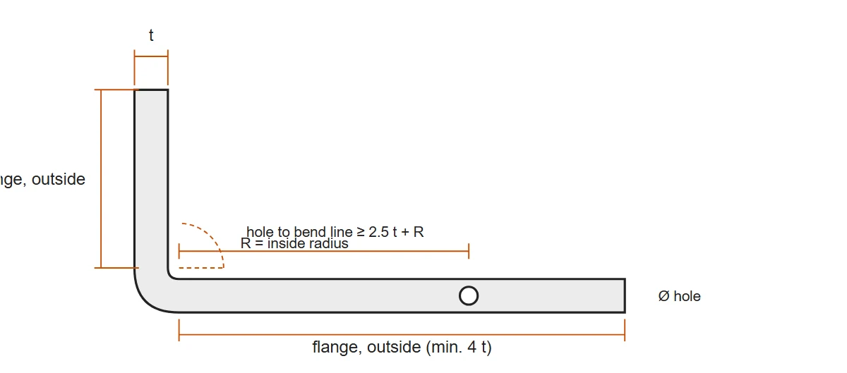
Give the outside dimensions; the blank is calculated here. Brackets, channels, covers and boxes laser cut and folded from 1 piece in steel, stainless and aluminium; the radius follows the table, the flat pattern is ours to work out. Drawing back for approval, quote in 12 hours.
Minimum flange, hole to bend, relief and spacing
A flange must be at least 4 × the thickness long on the outside for air bending and 6 × for bottoming, a hole stays 2.5 × t plus the inside radius from the bend line and a slot 4 × t plus the radius, and a bend relief is at least 1 × t wide and R + 0.5 × t long; in 2 mm sheet that is an 8 mm flange, a hole 7 mm from the bend at a 2 mm radius and a 2 mm wide relief.
| Feature | Rule | In 2 mm sheet | In 3 mm sheet | Why |
|---|---|---|---|---|
| Minimum flange, air bending | 4 × t outside | 8 mm | 12 mm | A shorter leg slips off the die and bends out of angle |
| Minimum flange, bottoming | 6 × t | 12 mm | 18 mm | The die needs more leg to coin the radius |
| Hole to bend line | 2.5 × t + R | 7 mm at R 2 | 10.5 mm at R 3 | Closer and the hole stretches into an oval |
| Slot to bend line | 4 × t + R | 10 mm at R 2 | 15 mm at R 3 | A slot deforms sooner than a round hole |
| Bend relief width | ≥ 1 × t | 2 mm | 3 mm | Stops the sheet tearing at the end of the bend |
| Bend relief length | ≥ R + 0.5 × t | 3 mm at R 2 | 4.5 mm at R 3 | Reaches past the bend zone |
| Distance between two bends | ≥ 3 × t | 6 mm | 9 mm | The second bend needs a flat to sit on the die |
| Countersink to bend line | ≥ 3 × t | 6 mm | 9 mm | The countersink cone collapses in the bend zone |
K-factor and springback by material
The K-factor places the neutral line in the thickness and sets how much material the bend consumes: 0.44 for mild steel, 0.45 for stainless, 0.38 to 0.42 for soft aluminium, 0.42 to 0.45 for 6061-T6 and 0.35 to 0.40 for brass and copper in air bending with a V-die of 6 to 8 × t. Springback is compensated by over-bending: 2 to 4° on steel, 4 to 7° on stainless, 2 to 10° on aluminium depending on the temper.
| Material | K-factor | Springback to allow for | Where the neutral line sits |
|---|---|---|---|
| Mild steel S235, 1018, A36, DC01 | 0.44 | 2–4° | 0.44 of the thickness in from the inside face |
| Stainless 304 / 1.4301, 316 / 1.4404 | 0.45 | 4–7° | 0.45 of the thickness in from the inside face |
| Aluminium 5052-H32 / 5754 | 0.38–0.42 | 2–6° | 0.38–0.42 of the thickness in from the inside face |
| Aluminium 6061-T6 / 6082-T6 | 0.42–0.45 | 4–10° | 0.42–0.45 of the thickness in from the inside face |
| Aluminium 3003-H14 | 0.38–0.42 | 2–4° | 0.38–0.42 of the thickness in from the inside face |
| Brass and copper, half hard | 0.35–0.40 | 2–4° | 0.35–0.40 of the thickness in from the inside face |
Bend allowance and bend deduction: a worked example
The bend allowance for a 90° bend in 2 mm mild steel at a 2 mm inside radius with K = 0.44 is 4.52 mm, the bend deduction is 3.48 mm, and a bracket with two 50 mm outside legs is cut from a 96.52 mm flat blank. The formulas are BA = π/180 × angle × (R + K × t) and BD = 2 × (R + t) × tan(angle/2) − BA; the blank is calculated from your outside dimensions, so the drawing you send shows only the finished part.
| Step | Formula | Value |
|---|---|---|
| Bend allowance BA | π / 180 × 90 × (R + K × t) = 1.5708 × (2 + 0.88) | 4.52 mm |
| Outside setback OSSB | (R + t) × tan(90° / 2) = 4 × 1 | 4.00 mm |
| Bend deduction BD | 2 × OSSB − BA = 8 − 4.52 | 3.48 mm |
| Flat blank for two 50 mm outside legs | 50 + 50 − BD | 96.52 mm |
| Same part in 2 mm stainless, K 0.45 | BA = 1.5708 × (2 + 0.90) = 4.56; BD = 3.44 | 96.56 mm blank |
| Same part in 2 mm 5052, R 2, K 0.40 | BA = 1.5708 × (2 + 0.80) = 4.40; BD = 3.60 | 96.40 mm blank |
A bracket the catalogue does not list, in 2, 10 or 100 pieces. The same folded part is quoted at 1, 10 and 100 pieces in one reply; from a few thousand a stamping die is quoted alongside. The programme is kept for the reorder.
What a laser-cut and folded part holds
A folded part holds about ±0.5 mm on a dimension across one bend and ±1° on the angle, with the holes and the outline at ±0.1 mm from the laser; a leg that must hold ±0.1 mm is milled from solid instead, which is the comparison on the custom brackets page.
| Dimension | Typical tolerance | Note |
|---|---|---|
| Hole diameter and outline, cut flat | ±0.1 mm | Before bending; the laser figure |
| Dimension across one bend | ±0.5 mm | Flange length, outside to outside |
| Dimension across two bends | ±0.8 mm | A channel's inside width; use one datum leg |
| Bend angle | ±1° | Springback is compensated per material |
| Hole to bend line | ±0.3 mm | The hole moves with the bend |
| Flatness of a leg | 0.5 mm per 100 mm | Thin wide legs bow slightly |
| Leg that must hold ±0.1 mm | Milled from solid | See custom brackets, machined or folded |
Will it fit, same but different, no drawing, second source
Will the bent part fit? Checks before you order
A dimension across a bend holds ±0.5 mm, so a channel that must slide over a 50 mm rail is drawn at 51 mm inside, not 50.2; a hole 5 mm from a bend line in 2 mm sheet will oval, so it is moved to 7 mm or cut after bending. A 6061-T6 leg bent at a 2 mm radius in 2 mm sheet cracks on the outside; the same part in 5052 does not, and the drawing is checked for that before the quote. The flange must be at least 4 × t, so a 3 mm part cannot carry a 10 mm lip.
Same bracket, but one detail changed
The same bracket with a longer leg, a second bend to make a Z, two more slots, in stainless for a wash-down line or in 3 mm instead of 2 mm keeps its programme and changes the blank; the new radius and the new blank are worked out here and the drawing comes back for approval. A bracket first folded in 2 pieces and later wanted in 200 is run from the same file.
No drawing: give the outside dimensions and the thickness
For a bent part the drawing is the finished shape: the outside length of each leg, the angle, the thickness, the hole positions on each leg from the outside edge, and the material; the flat blank with the bend allowance is our calculation, not yours. A photo of the old bracket square-on against a ruler, plus the calliper numbers, is enough; a bracket that has sprung or cracked is measured on the mating part instead.
Supplier stopped, minimum too high, lead time too long
A folded part is specified by its drawing, material, thickness, radius and finish, so a second source starts from the drawing; where the previous supplier asked for 500 pieces, the same bracket is made from 1 piece here with the unit price stepping down at 10 and 100. The first pieces check the fit; the repeat is run from the kept programme.
Where the catalogue bracket stops
A standard bracket in a catalogue size is cheaper from stock; a folded part becomes a job for the brake when the legs, the holes, the material or the radius are yours.
| You need | From stock? | How it is made |
|---|---|---|
| A standard L or U bracket in a catalogue size and hole pattern | Yes — stock item | Buy it from stock; a one-off fold cannot beat a stock bracket on price |
| The same bracket with your holes, your leg lengths or in 316 | No | Laser cut and folded from 1 piece; the radius from the chart, the blank from your outside dimensions |
| A bent leg that must hold ±0.1 mm or carry a gusset | No | Milled from solid; compared route by route on the custom brackets page |
| A 6061-T6 bracket with a sharp 1 × t bend | Yes — stock item | It cracks; made in 5052 at 1 × t, or in 6061 at 2 × t, or milled |
| A 10 mm steel bracket with a bend | No | Folded at R 10 on a heavy brake, or welded from two laser-cut plates, or milled |
| The same bracket in five thousand pieces | No | Laser and fold for the first hundreds; a progressive die quoted for the volume (custom stamped parts) |
The cluster: laser cutting thickness and tolerance chart · laser-cut plates with holes and cutouts · laser-cut shims and washers · replacement guards and cover plates · custom brackets, machined or folded · custom stamped parts · ISO 2768 general tolerances · 6061 vs 6082.
Frequently asked questions about bend radius and folded parts
About 2.4 to 3 mm inside radius for 5052-H32 (0.8 to 1 × thickness) and 4.5 to 6 mm for 6061-T6 (1.5 to 2 × thickness); bending 6061-T6 tighter cracks the outside of the bend. Along the grain the radius goes up by half again. 5052 is the alloy for a bent aluminium part; 6061 is cut flat or bent at a generous radius.
1 × thickness for mild steel, so a 2 mm bracket bends at a 2 mm inside radius, and 1 to 1.5 × thickness for stainless 304 and 316, so 2 mm stainless bends at 2 to 3 mm. The radius on a press brake comes from the V-die, about one sixth of the die opening, so the drawing states the radius and the die is chosen to give it.
4 times the thickness measured on the outside, so a 2 mm part needs an 8 mm flange and a 3 mm part a 12 mm flange; bottoming needs 6 times. A shorter flange slips off the die and bends out of angle. A hole should sit 2.5 × t plus the inside radius from the bend line, 7 mm in a 2 mm part at a 2 mm radius, or it stretches into an oval.
The K-factor is where the neutral line sits in the thickness, 0.44 for mild steel, 0.45 for stainless, 0.38 to 0.42 for soft aluminium; the bend allowance is the length of material in the bend, π/180 × angle × (R + K × t). For a 90° bend in 2 mm steel at a 2 mm inside radius that is 4.52 mm, the bend deduction is 3.48 mm, and a part with two 50 mm outside legs is cut from a 96.52 mm blank. The blank is calculated from your outside dimensions, so the drawing can carry the finished part only.
About ±0.5 mm on a dimension across one bend and ±1° on the angle, with ±0.1 mm on the holes and the outline cut before bending; two bends stack to about ±0.8 mm. Where a leg must hold ±0.1 mm the bracket is milled from solid instead, which is the comparison on the custom brackets page.
Yes, from 1 piece. A press brake needs a programme and a die, not a tool made for the part, so one bracket is folded as readily as a hundred; the quantity moves the price through the sheet it shares and the set-up it carries. From a few thousand pieces a bending die or a progressive stamping die is quoted alongside.