What Makes a Screw an Adjustment Screw
Any set screw can be turned to move something; an adjustment screw is one whose movement is the specification. Four features carry that: the pitch (travel per turn), the tip (what it pushes on and how), the thread fit (backlash) and the hardness (wear over thousands of adjustments). The rest of the screw — drive, length, material, finish — follows from where it goes. The catalogue covers a few combinations well: 1/4-80 and 100 TPI adjusters for optical mounts from the optics catalogues, ISO fine-pitch set screws from every fastener house. Off that grid, the screw is made to a drawing, and this page is the drawing's vocabulary.
Thread Pitch and Adjustment Travel — Per Turn and Per Degree
Axial travel per revolution is the pitch; per degree of rotation it is the pitch divided by 360. The table converts the common adjuster pitches, metric and inch, so a drawing can state the resolution it is buying.
| Thread / pitch | Pitch | Travel per revolution | Travel per 1° | Note |
|---|---|---|---|---|
| M3 × 0.5 (coarse, ISO 261) | 0.5 mm | 500 µm | 1.39 µm | ordinary set screw |
| M3 × 0.35 (fine, ISO 261) | 0.35 mm | 350 µm | 0.97 µm | standard fine pitch |
| 40 TPI | 0.635 mm | 635 µm | 1.76 µm | coarse adjuster, older mounts |
| 64 TPI | 0.3969 mm | 397 µm | 1.10 µm | medium adjuster |
| M3 × 0.30 | 0.3 mm | 300 µm | 0.83 µm | ultra-fine, special; outside ISO 261 |
| M3 × 0.25 (ultra-fine, special) | 0.25 mm | 250 µm | 0.69 µm | the M3 × 0.25 page on this site; outside ISO 261 |
| 80 TPI (e.g. 1/4-80, 6-80) | 0.3175 mm | 318 µm | 0.88 µm | the standard optical-mount adjuster |
| M3 × 0.20 | 0.2 mm | 200 µm | 0.56 µm | ultra-fine, special |
| 100 TPI (e.g. 1/4-100, 3/16-100) | 0.254 mm | 254 µm | 0.71 µm | fine optical adjuster |
| M4 × 0.15 | 0.15 mm | 150 µm | 0.42 µm | ultra-fine, special |
| M6 × 0.125 | 0.125 mm | 125 µm | 0.35 µm | ultra-fine, special |
| 200 TPI | 0.127 mm | 127 µm | 0.35 µm | differential-class adjuster |
| M3 × 0.05 / 508 TPI | 0.05 mm | 50 µm | 0.14 µm | specialist matched screw-and-bushing sets; not made here |
These are geometric values from the pitch alone. The positioning resolution, repeatability and accuracy of a mechanism also depend on thread fit and backlash, preload, tip geometry and the contact surface, the stiffness of the mount and the bearing of the moving part; an M3 × 0.25 screw does not “give 0.69 µm accuracy” — it gives 0.69 µm of travel per degree, and the mechanism decides what of that is repeatable. Matched screw-and-bushing sets at 200 TPI and finer exist because a loose 6g / 6H fit would lose more than the pitch gains.
Thread Sizes — Standard Fine, Ultra-Fine Specials, Inch Adjusters
| Family | Sizes | Note |
|---|---|---|
| Metric fine (ISO 261) | M2 × 0.25, M3 × 0.35, M4 × 0.5, M5 × 0.5, M6 × 0.75, M8 × 1 / 0.75, M10 × 1.25 / 1 / 0.75 | standard series; taps, dies and gauges stocked |
| Metric ultra-fine (special) | M2 × 0.2, M2.5 × 0.2, M3 × 0.25, M3 × 0.2, M4 × 0.25, M4 × 0.15, M6 × 0.25, M6 × 0.15, M6 × 0.125 | outside ISO 261; single-point threaded, custom gauges; our ball-tip range covers M2 × 0.2 to M12 × 0.25 in 80 standard lengths (table below) |
| Inch fine adjuster threads | 6-80, 8-80, 1/4-80, 3/16-100, 1/4-100 | 80 TPI is the optical-mount standard (mirror and kinematic mounts); 100 TPI the finer class |
| Inch ultra-fine and matched sets | 1/4-200, 1/4-254, 1/4-508, M3 × 0.05 | supplied as matched screw-and-bushing pairs by the specialist makers; made to order only with the bushing |
| Other diameters and pitches | any diameter with any pitch the drawing gives | evaluated per drawing, material, quantity and tolerance |
Ultra-fine pitches are not in ISO 261 and no tap or die exists for them off the shelf: the thread is single-point cut, the gauge is made for the job, and the pitch is what the drawing says. Other diameters and pitches are evaluated from the drawing, the material, the quantity and the tolerance; a thread that exists nowhere else is a normal request here, not a problem. The metric-to-inch crosswalk for the coarse and fine series is on the metric vs imperial thread chart.
Ball-Tip Ultra-Fine Set Screws — Our Size Range, M2 × 0.2 to M12 × 0.25
The hex-socket, ultra-fine-pitch set screw with a hardened steel ball in a 304 / 1.4301 stainless steel body is made here as a range, not a one-off: eleven thread sizes and eighty standard lengths, with the ball diameter, nose and socket fixed per thread. The drawing below is ours and the letters match the table; a length that is not in the list, a different ball, a slot instead of a socket or a specified hardness is a drawing change on the same body.
| A — thread | B — standard lengths | C hex A/F | D ball ø | E nose ø | F nose length | G ball protrusion |
|---|---|---|---|---|---|---|
| M2 × 0.2 | 3, 4, 4.6, 5, 6, 8, 10, 12.5, 15, 17.5, 20 | 1.3 | 1.5 | 1.75 | 0.65 | 0.2 |
| M2.5 × 0.25 (6 mm) | 6 | 1.3 | 1.5 | 1.75 | 0.65 | 0.2 |
| M2.5 × 0.25 | 6.5, 8, 10, 12, 15, 17.5, 20 | 1.5 | 1.5 | 1.92 | 0.65 | 0.5 |
| M3 × 0.25 | 8, 10, 12, 15, 17.5, 20, 25 | 1.5 | 2 | 2.4 | 0.9 | 1.27 |
| M4 × 0.2 | 8, 10, 12.5, 15, 17.5 | 1.5 | 2 | 2.4 | 0.9 | 1.27 |
| M4 × 0.25 | 8, 10, 12.5, 15, 17.5, 20, 25, 30, 35, 40, 45, 50 | 2 | 3 | 3.4 | 1.4 | 1.58 |
| M5 × 0.25 | 8, 10, 12.5, 15, 17.5, 20, 25, 30, 35, 40, 45, 50 | 2 | 4 | 4.4 | 1.9 | 1.77 |
| M6 × 0.25 | 8, 10, 12.5, 15, 17.5, 20, 25, 30, 35, 40, 45, 50, 75 | 2 | 4.76 | 5.15 | 2.28 | 2.24 |
| M8 × 0.25 | 20, 25, 30, 35, 40, 50, 60, 75 | 3 | 6 | 6.4 | 2.9 | 3.4 |
| M10 × 0.25 | 50, 75 | 3 | 8 | 8.4 | 3.9 | 3.9 |
| M12 × 0.25 | 75, 100 | 4 | 10 | 11 | 4.9 | 4.9 |
Eighty size combinations in the standard range; M2.5 × 0.25 has a 6 mm version with the M2 nose (1.3 mm hex, 0.2 mm protrusion) and longer versions with the 1.5 mm hex. Standard construction: 304 / 1.4301 stainless steel body with a hardened steel ball pressed into the nose. Lengths, tips and drives outside the table are made to drawing; a through-hardened alloy steel body (as on the M3 × 0.25 page) is a material change on the same range. The M3 × 0.25 row is detailed on the M3 × 0.25 page.
Tip Geometry — What the Screw Pushes On, and How
| Tip | Construction | What it does | Limit |
|---|---|---|---|
| Ball tip, pressed ball | hardened stainless or steel ball pressed into a drilled end | single-point contact through misalignment, lowest wear; the optical-mount default | ball must be pressed, not glued (adhesive outgasses) |
| Ball tip, turned spherical | one-piece screw with a turned and polished radius | one piece, no ball to lose, hardenable with the body | radius accuracy is the machining |
| Rounded (radius) tip | large radius, one piece | pushes on a flat without indenting; less sensitive to squareness than a flat | the general adjuster tip |
| Flat tip | square, chamfered end | largest contact area, least indentation on a hardened pad | needs a square, hard pushed surface |
| Cone point | 90° or 118° cone | locates in a dimple or centre | positioning, not adjustment |
| Dog point | cylindrical pilot | locates in a hole or slot | stop and locating screws |
| Soft tip | brass, nylon, copper or PEEK insert | no marking of the pushed surface | lower load, replaceable insert |
| Swivel pad | a pad on a ball joint | full-face contact on a non-square surface | clamping, not fine positioning |
Ball-tip set screw is not a ball plunger. A ball-tip screw is solid: a fixed ball or a turned sphere on the end, and it stays where it is turned to. A ball plunger has a spring and a free ball inside a threaded body: the ball gives under load and returns, for detents and light constant force, and it positions nothing. An RFQ for “ball screw” can also mean a recirculating ball leadscrew, which is a third thing; the drawing or the mating part tells which.
Drive Styles at Small Diameters
| Drive | Practical from | Advantage | Limit |
|---|---|---|---|
| Slotted | M2–M6 | cheapest to cut; fits a headless screw at any diameter | low torque; slot can be damaged |
| Hex socket | M3 and up (1.5 mm key at M3) | highest torque of the headless drives, standard key | wall thickness at M3 × 0.25 is thin; socket depth limited on short screws |
| Torx / hexalobular | M3 and up | high torque, no cam-out | special key |
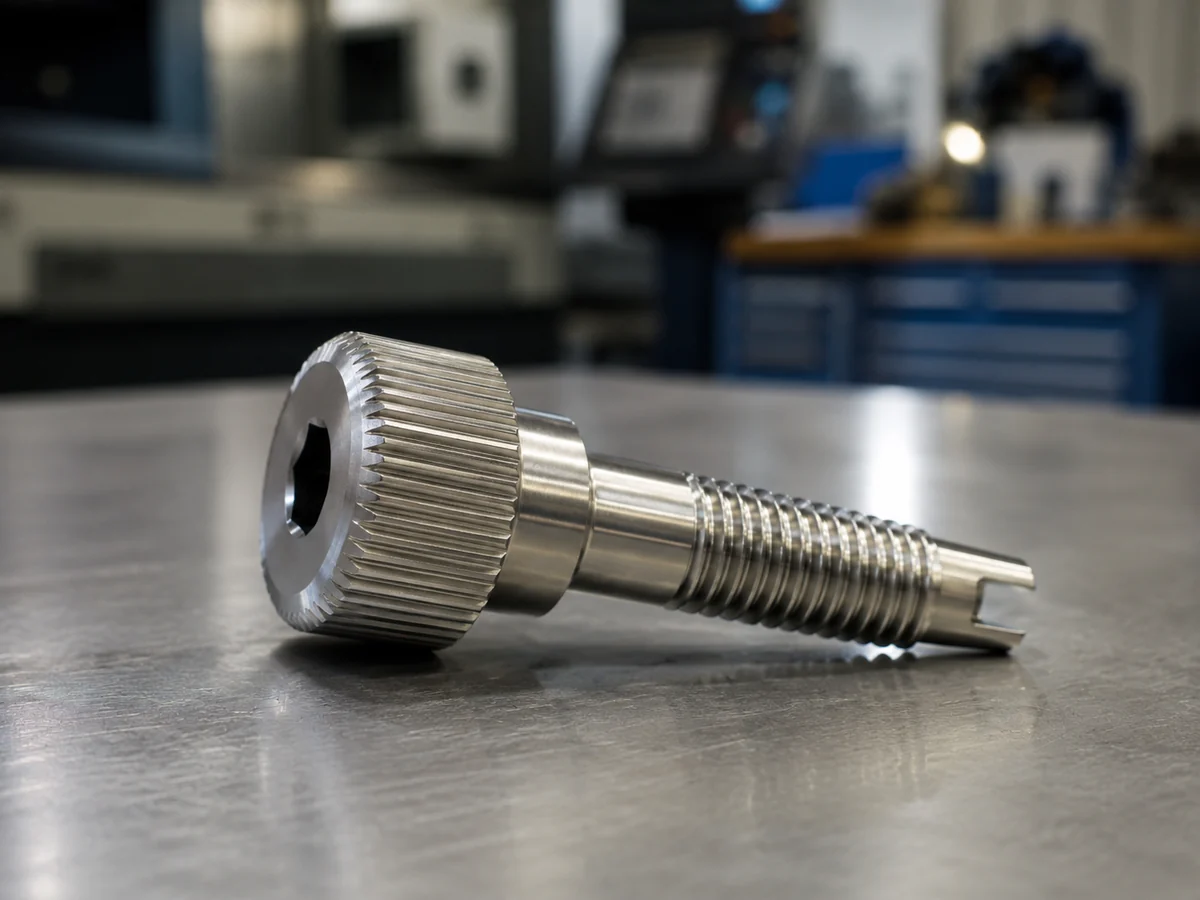
| Knurled head | any | finger adjustment without a tool, fixed knob | adds a head; see thumb screws |
| Flats / external hex | M4 and up | spanner adjustment, lockable with a nut | adds length |
At M3 the choice is a slot or a 1.5 mm hex socket. The slot is cheaper and leaves the full wall; the socket takes more torque but its corners sit close to the minor diameter of an M3 × 0.25 thread (2.69 mm), which is why a slotted drive is the low-cost answer at this size. Above M4 the hex socket is the default and Torx the upgrade.
Material and Hardness
| Material | Hardness | Where it is used |
|---|---|---|
| Stainless 303 / 1.4305 (304 / 1.4301 where a free-cutting grade is not allowed) | unhardened, about 20 HRC equivalent | the instrument and optics adjuster: machines to a fine thread cleanly, no corrosion, non-magnetic; ball pressed in for a hard tip |
| Stainless 316L / 1.4404 | unhardened | corrosive or washdown environments |
| 17-4 PH / 1.4542, H900 | about 40–44 HRC | the stainless choice when the screw body itself must be hard |
| Alloy steel 42CrMo4 / 4140, through-hardened | HRC 50–55 on request, class 45H (about 45 HRC) as standard | wear-resistant ball tips and threads for repeated adjustment; black oxide or plated |
| Tool steel / bearing steel 100Cr6 | HRC 58–62 | hardest one-piece tips; short screws only, ground after hardening |
| Brass CuZn39Pb3 / C360 | soft | adjusters running in steel where the screw is the sacrificial part; non-magnetic, non-sparking |
| Titanium Grade 5 | about 36 HRC | non-magnetic, weight-critical, vacuum |
Through-hardening treats the whole screw; selective (induction or tip-only) hardening treats the ball or nose and leaves the drive tough. Both distort: a hardened screw grows slightly on the thread and can bow along its length, so short screws are threaded before hardening with the growth compensated, and long or highest-accuracy screws are ground after. Hardness above about 55 HRC on a one-piece screw brings brittleness at the drive; a pressed hardened ball in a 303 body avoids the problem where the body does not need to be hard. Grade names cross to their European, Japanese and Chinese equivalents on the 4140 / 42CrMo4 and stainless steel charts.
How an Ultra-Fine Screw Is Made and Checked
| Route | Where it applies | Limit |
|---|---|---|
| Cut thread (single-point, CNC or Swiss lathe) | any pitch, any diameter, prototypes and unusual pitches; the route for ultra-fine specials | slower per piece; thread surface is the tool's finish |
| Rolled thread | good surface, work-hardened flanks, efficient from thousands of pieces | needs a rollable material and pitch; dies per pitch; not for hardened blanks |
| Ground thread | highest pitch accuracy and finish; the route for hardened screws and matched sets | highest cost; specialist process |
| Thread after hardening vs before | cut before hardening on short screws (growth compensated), ground after on long or highest-accuracy screws | hardening distorts; straightness checked on the finished part |
Depending on pitch, material, hardness, tolerance and quantity the screw is produced by CNC or Swiss turning with single-point threading, by thread rolling, by grinding or by a combination, with tip turning or ball pressing, socket broaching or slot cutting, heat treatment and finishing following; the quote names the route. Inspection: thread ring gauge to the class on the drawing, pitch and tip on a projector, hardness by Rockwell on a batch sample, straightness by rolling, pre-shipment photos on request. The undercut behind a thread that must run out cleanly is sized on the thread undercut chart.
Where Precision Adjustment Screws Go
| Application | What the screw does | What it needs |
|---|---|---|
| Optical and photonic mounts — mirror mounts, lens mounts, kinematic mounts, laser alignment, translation and rotation stages | tilts or translates an optic by micrometres and holds it | 80 or 100 TPI or 0.25 mm pitch, hardened ball tip on a hardened pad, low backlash, 303 stainless body, often a bronze bushing |
| Metrology and measuring equipment — gauge heads, calibration fixtures, comparator stands, probe alignment | sets a datum or a zero and stays there through thousands of readings | hardened tip, fine pitch, thread class 4g6g or a locknut, repeatability over resolution |
| Sensor and camera positioning — sensor mounts, alignment of encoders, proximity switches, camera modules | aligns a sensor to a target and locks | fine pitch, rounded tip, a lock feature (nut, nylon patch or second screw) |
| Jigs, fixtures and automation — stop screws, levelling screws, precision locating screws, tool setters | sets a hard stop or a level to a repeatable position | hardened flat or ball tip, hex or slot drive, a jam nut |
| Laboratory and scientific instruments, legacy equipment | replaces an adjuster that the instrument maker no longer supplies | a sample to measure from, the same pitch and tip, often a small quantity |
Where the Catalogue Stops — Stock Adjusters, or Screws to Your Drawing
| What you need | In the catalogue? | What we make |
|---|---|---|
| A 1/4-80 or 100 TPI adjuster in a catalogue length with a ball tip, for a mirror or kinematic mount | Yes — optics catalogues | Buy it from stock at the optics catalogue: they are cheap and made in volume, and we say so instead of quoting. Standard parts: ask us too — we may have them in stock. |
| An M3 × 0.35 or M6 × 0.75 fine-pitch set screw in a standard length | Yes — fastener catalogues | Buy them from stock: ISO 261 fine-pitch set screws are in every fastener catalogue. Standard parts: ask us too — we may have them in stock. |
| An M3 × 0.25 set screw, 8 mm long, ball tip, hardened HRC 50–55, slotted or hex, 100 to 10,000 pieces | No | Made to drawing; the full specification is on the M3 × 0.25 adjustment screws page. |
| A catalogue pitch in a length, tip or drive the catalogue does not carry | No | Turned to drawing in the same pitch; the catalogue part is the reference, the drawing adds the change. |
| An adjustment screw from an old instrument, microscope stage or gauge that is no longer made | No | Measured from the sample (pitch on a comparator), drawn, made; see replacement fasteners from a sample. |
| A hardened M3 × 0.25 threaded rod, 1,000 mm long, for the customer's own secondary machining | Review | Possible as ground thread on a hardened blank in short lengths; a metre of hardened ultra-fine rod is not a straight part after heat treatment, and the finished screws are usually the better buy — see custom threaded rods. |
What We Need to Quote a Precision Screw
1. Thread diameter and pitch (or TPI) 2. Overall length and threaded length 3. Tip style and, for a ball tip, the ball diameter 4. Drive: slot, hex socket, Torx, knurled head 5. Material, or the environment and we propose one 6. Hardness, if the tip or body must be hard 7. Thread tolerance class (6g unless stated) and the mating part, if backlash matters 8. Surface finish or plating 9. Quantity now and expected later 10. A drawing, photo, sample or the instrument it goes in. No CAD file is required; a dimensioned approval drawing comes back before machining, and the quote within 12 hours.
The bushing an adjustment screw runs in is a part of its own: a flanged brass bushing with the same 0.25 mm pitch thread, from M3 × 0.25 on a 4.5 mm mounting diameter to M6 × 0.25 on 9.5 mm, pressed or bonded into the mount. The size table, the tap drills and the screw-and-bushing pair are on fine-thread bushings. Where the setting has to hold through transport or vibration, the locking threaded bushing screws into a tapped hole and holds the screw with an M2 nylon-tip screw in the side of its hex.
Related: M3 × 0.25 adjustment screws · custom set screws and grub screws · thumb and knurled screws · custom threaded rods · ACME and trapezoidal lead screws · custom fasteners.
Precision Adjustment Screw FAQ
Three things, all on the drawing. Pitch: a standard M3 set screw is 0.5 mm, an adjustment screw is 0.35 mm, 0.25 mm or finer, so one turn moves the tip 250 µm instead of 500 µm and one degree moves it 0.7 µm. Tip: a standard set screw has a cup or flat point to grip; an adjuster has a hardened ball or rounded tip to push on a surface without marking it and to keep the contact at one point when the parts are not square. Fit: a standard set screw is 6g against a 6H nut and rattles; an adjuster is specified 6g or tighter and often runs in a bronze bushing or a matched nut to take out backlash. The catalogue set screws and their point styles are on the set screws page; this page is the adjuster.
Fine threads are the ISO 261 fine series (M3 × 0.35, M6 × 0.75) and the UNF / UNEF series; ultra-fine threads are pitches below those — 0.3, 0.25, 0.2, 0.15, 0.125 mm in metric, 80 to 200 TPI (0.317 to 0.127 mm) in inch — outside any standard series and made as specials. The resolution follows the pitch directly: axial travel per turn equals the pitch, and per degree equals pitch ÷ 360, so M3 × 0.25 gives 0.69 µm per degree against 1.39 µm for M3 × 0.5. The number is geometry only; what a mechanism resolves in practice also depends on thread fit, backlash, preload, tip geometry and the stiffness of the mount, which is why the same screw is specified with a thread class and often a matched bushing.
Yes. M3 × 0.25 and M6 × 0.25 are in our standard ball-tip range (M2 × 0.2 to M12 × 0.25, 80 lengths, table on this page); pitches outside it are single-point threaded on a CNC or Swiss-type lathe with a custom insert and checked with a custom thread gauge, which is why they are made to order rather than stocked. Hardening: alloy steel screws are through-hardened after threading to HRC 50–55 (standard grub screws are class 45H, 450 HV minimum, about 45 HRC), which grows the thread slightly and can bow a long screw; on short screws the thread is cut to compensate, on long ones the thread is ground after hardening. Stainless 303 is used unhardened for instrument adjusters; 17-4 PH hardened to about 40 HRC is the stainless alternative when a hard tip is needed. The specific case is on the M3 × 0.25 adjustment screws page.
Ball tip (a hardened ball pressed into the end, or a turned spherical end) where the screw pushes on a flat or a V that is not square to the screw: it keeps a single point of contact through angular misalignment and rolls rather than scrapes. Rounded (turned radius) where a full ball is not needed and the part must be one piece. Flat where the pushed surface is hardened and square, for the largest contact area and least indentation. Cone where the screw must locate in a dimple. A soft nylon or brass tip where the pushed surface must not be marked. The ball tip is the default for optical and metrology mounts.
A ball-tip set screw is a solid screw with a fixed ball or spherical end: it moves when turned and stays where it is put. A ball plunger is a threaded body with a spring and a free ball inside: the ball retracts under load and returns, giving a detent or a constant light force, and it does not position anything. Drawings and RFQs confuse the two often; if the screw sets a position, it is a ball-tip screw, and if it clicks into a groove, it is a plunger.
6g is the usual ISO external tolerance class on the drawing (medium fit, the same class as a standard bolt); 4g6g or 4h are specified where backlash matters, and the mating nut or bushing is then specified with it. Inspection is by thread ring gauge (go / no-go) to the class, pitch checked on an optical comparator or thread micrometer, length and tip by micrometer and projector, hardness by Rockwell on a sample of the batch, straightness on long screws by rolling on a plate. Gauges for ultra-fine pitches are made for the job and are part of the first-order cost; reorders reuse them.
Yes. Send the screw, or photographs with the mating part, and the pitch is measured on a comparator (an 80 TPI thread against a 0.3 mm one is not told apart by eye), the diameter and length by micrometer, the tip radius by projector and the hardness by file test or Rockwell. The result is a drawing you approve before machining, and the drawing is kept for the next order; the route is the same as for any replacement fastener from a sample.
Minimum is 1 piece. From 1 to a few hundred the screws are turned one at a time on a CNC lathe and the price is dominated by setup and gauging; from about 1,000 the same drawing moves to a Swiss-type automatic and the unit price falls; at 10,000 the thread can be rolled instead of cut where the pitch and material allow, which changes the process and needs a first-article approval. The first quote states which route each quantity takes, and a 100-piece order is a normal first order, not a prototype charge.