EKINSUN LTD is a custom parts manufacturer in Shenzhen that machines adapter and mounting plates to order from 1 piece, from a drawing, two measured hole patterns or the parts themselves.
Two hole patterns, one plate: what the plate has to know
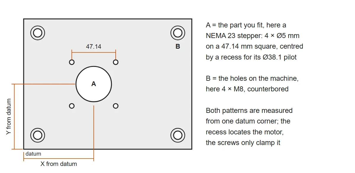
An adapter plate needs both hole patterns measured from the same corner, the feature that centres the part, such as the Ø38.1 mm pilot of a NEMA 23 motor, and the room for screw heads, shafts and cables on both faces. Get those right and the part bolts on the first time; miss one and the plate is remade.
| What we need | Why it matters | How to give it |
|---|---|---|
| Pattern A: the part you fit | Hole positions, sizes, threads and any pilot | The datasheet drawing, or measurements from the part |
| Pattern B: the machine's holes or slots | Tapped holes, through holes, T-slots or profile slots | Measured from one corner of the mounting face |
| How A sits relative to B | Offset, rotation, height of the shaft or the sensor | A sketch with the two centres and one dimension between them |
| What centres the part | Pilot recess, spigot or two dowels keep it aligned; bolts only clamp | Pilot diameter, dowel diameter, which faces locate |
| Room for heads, shaft and cables | Counterbore depths, shaft clearance, connector exits | Screw lengths, shaft length, which side the cable leaves |
| Load and stiffness | Thickness and material | What the part weighs or pulls, how far it overhangs |
Standard hole patterns a mounting plate is built around
Stepper motors, quarter-turn valve actuators, linear rails and optical parts each follow a published hole pattern, from the 31 mm square of a NEMA 17 to the 25 mm grid of a metric breadboard, so a plate for one of them starts from the standard and only the machine side is measured.
Stepper and servo plates: NEMA 17, 23 and 34
A NEMA 23 stepper has four Ø5 mm through holes on a 47.14 mm square and a Ø38.1 mm pilot, so its mounting plate carries those four holes and a 38.1 mm recess or bore that centres the motor. Servo motors of the same frame size often use other patterns, so a servo is measured from its datasheet.
| Frame | Hole square | Holes | Pilot Ø | Shaft |
|---|---|---|---|---|
| NEMA 17 (42 mm face) | 31.0 mm (1.220 in) | 4 × M3 tapped (4-40 UNC on US-built motors) | Ø22 mm (0.866 in) | 5 mm |
| NEMA 23 (57 mm face) | 47.14 mm (1.856 in) | 4 × Ø5 mm through (0.195 in) | Ø38.1 mm (1.500 in) | 6.35 mm (1/4 in) on most; measure yours |
| NEMA 34 (86 mm face) | 69.6 mm (2.74 in) | 4 × Ø5.5 mm through (0.218 in) | Ø73 mm (2.875 in) | 9.525 mm (3/8 in) or 14 mm; measure yours |
An industrial motor with a NEMA C-face, an IEC B5 or B14 flange or an SAE pump flange swapped onto an old machine is covered on motor adapter rings and plates; robot tool flanges to ISO 9409-1 on custom robot parts.
Send both patterns, or the datasheet and a photo of the machine face. Stepper, servo, actuator, rail, sensor and camera plates from 1 piece; the pilot recess, dowels and counterbores are in the same quote. The approval drawing shows both patterns; the price follows within 12 hours.
Valve actuator plates: ISO 5211 flanges F03 to F16
ISO 5211 fixes the bolt circle and thread of every quarter-turn actuator flange: F05 is four M6 on a 50 mm circle, F07 four M8 on 70 mm and F10 four M10 on 102 mm, so an F05-to-F07 adapter plate carries both circles on one centre line. The spigot diameter d2 centres the actuator where the flange has one.
| Flange | Bolt circle | Bolts | Flange Ø d1 | Spigot Ø d2 |
|---|---|---|---|---|
| F03 | 36 mm | 4 × M5 | 46 mm | 25 mm |
| F04 | 42 mm | 4 × M5 | 54 mm | 30 mm |
| F05 | 50 mm | 4 × M6 | 65 mm | 35 mm |
| F07 | 70 mm | 4 × M8 | 90 mm | 55 mm |
| F10 | 102 mm | 4 × M10 | 125 mm | 70 mm |
| F12 | 125 mm | 4 × M12 | 150 mm | 85 mm |
| F14 | 140 mm | 4 × M16 | 175 mm | 100 mm |
| F16 | 165 mm | 4 × M20 | 210 mm | 130 mm |
The square or double-D drive between actuator and valve stem is a separate coupling, machined to both stems; see rigid shaft couplings. Flanges F25 and larger carry eight or more bolts and are drawn from the actuator datasheet.
Valve actuator change? Give the two flange codes. F05 to F07, F07 to F10 or a non-standard flange: the plate is drawn from the codes, the coupling from the two stems. Priced within 12 hours, from 1 plate.
Linear rail plates: hole pitch and screw size
A 15 mm profile rail of the HGR15 size is bolted with M4 screws every 60 mm, a 20 mm rail with M5 at 60 mm, a 25 mm rail with M6 at 60 mm and a 30 mm rail with M8 at 80 mm; a miniature 12 mm rail takes M3 every 25 mm. Rails from other makers use other pitches, so the pitch is measured over four or five holes and divided.
| Rail | Hole pitch | Screw | On the plate |
|---|---|---|---|
| 15 mm profile rail (HGR15 size) | 60 mm | M4 | 4 × M4 per 240 mm of rail |
| 20 mm profile rail (HGR20 size) | 60 mm | M5 | tapped M5 at 60 mm |
| 25 mm profile rail (HGR25 size) | 60 mm | M6 | tapped M6 at 60 mm |
| 30 mm profile rail (HGR30 size) | 80 mm | M8 | tapped M8 at 80 mm |
| Miniature 9 mm rail (MGN9) | 20 mm | M3 | tapped M3 at 20 mm |
| Miniature 12 mm rail (MGN12) | 25 mm | M3 | tapped M3 at 25 mm |
| Miniature 15 mm rail (MGN15) | 40 mm | M3 | tapped M3 at 40 mm |
Two parallel rails on one plate are machined in the same set-up, so their spacing and their reference edges relate to the machine, not to two separate measurements. The mounting face under a rail is milled flat, and the rail catalogue gives the flatness and height difference each accuracy class allows; the flatness values a plate can reach are on fixture and tooling plates.
Camera, sensor and optics plates
Optical breadboards use M6 holes on a 25 mm grid or 1/4-20 holes on a 1 in grid, and cameras mount on 1/4-20 or 3/8-16 UNC threads, so a camera or sensor plate is drilled to one of these on one side and to the machine on the other.
| Part | Standard | On the plate |
|---|---|---|
| Metric optical breadboard | M6 tapped holes on a 25 mm grid, 12.5 mm from the edge | Tapped M6 grid, or clearance holes to bolt onto one |
| Imperial optical breadboard | 1/4-20 UNC on a 1 in grid, 0.5 in from the edge | Tapped 1/4-20 grid, or matching clearance holes |
| Camera, light, small sensor | 1/4-20 UNC tripod thread | A 1/4-20 tapped hole or a clearance hole and a screw |
| Heavier camera, head, rig | 3/8-16 UNC | A 3/8-16 tapped hole, often beside a 1/4-20 and a locating pin |
Brackets that hold a proximity or photo sensor at an angle are on sensor mounting brackets.
Measuring a hole pattern on the part you already have
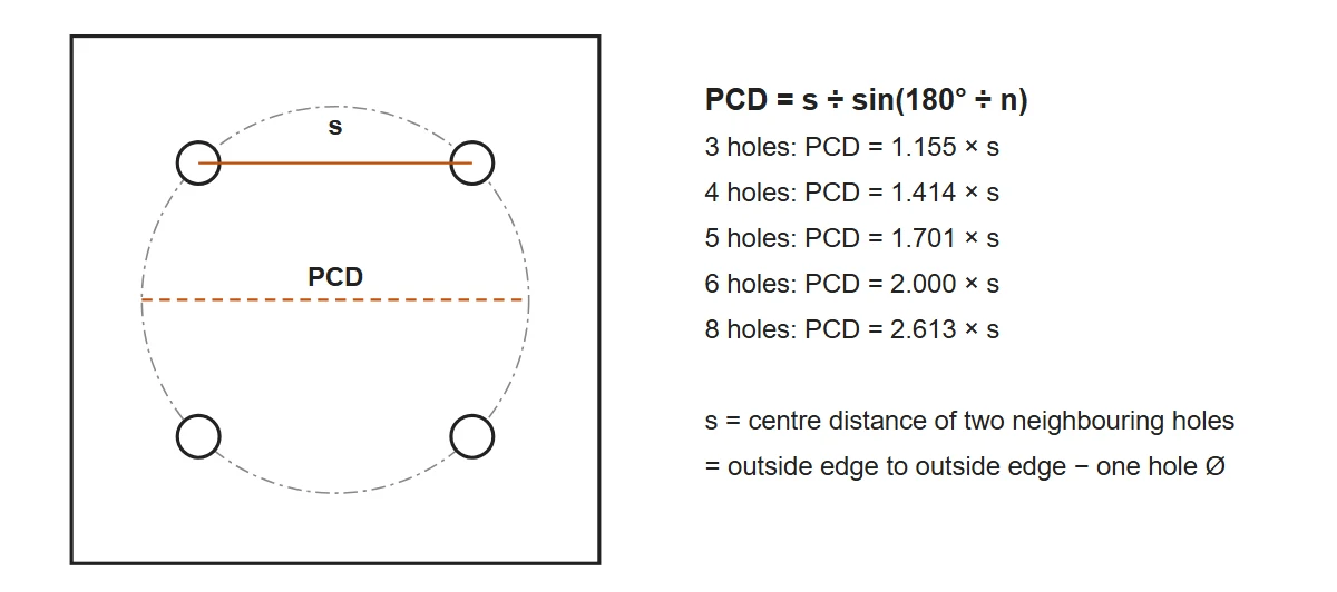
Four holes on a circle are measured across two neighbouring holes: the bolt circle is that centre distance times 1.414, for six holes twice the distance, for eight 2.613 times. The centre distance itself is the outside-edge-to-outside-edge measurement minus one hole diameter, which a calliper reads more reliably than a centre.
| Holes on the circle | Bolt circle (PCD) | Example: holes 50 mm apart |
|---|---|---|
| 3 | 1.155 × s | 57.8 mm |
| 4 | 1.414 × s | 70.7 mm |
| 5 | 1.701 × s | 85.0 mm |
| 6 | 2.000 × s | 100.0 mm |
| 8 | 2.613 × s | 130.7 mm |
A rectangular pattern is measured as X and Y from one corner of the face, with each hole's diameter and whether it is tapped or through. A photo taken square-on with a ruler in frame records the pattern for a check, and the part or the old plate posted to us removes the guesswork.
Bolted or located: when the plate needs a spigot or dowels
A clearance hole lets a part shift by the difference between hole and bolt, 1 mm on an M8 in a 9 mm hole, so a part that must stay aligned is centred by a spigot recess or by two H7 dowel holes, not by its bolts. A motor centred by its pilot in a recess keeps the coupling aligned; a sensor on two dowels goes back to the same place after service.
Two dowels: one round hole, one slot
Two dowels in two round holes jam when the hole spacing on the two parts differs by as little as 0.02 mm, so the second dowel hole is made as a short slot in the direction between them. ISO 8734 dowel sizes with their m6 tolerance are on the dowel pin size chart.
How thick an adapter plate should be
An aluminium plate needs about 1.44 times the thickness of a steel plate to be as stiff, because aluminium's modulus is about a third of steel's and plate stiffness rises with the cube of thickness. A plate that carries tapped holes also needs the thread depth: about 2 × d of full thread in aluminium, 16 mm for an M8, which is why plates with deep threads are thick or use inserts, explained on plates with tapped holes.
A real batch: flange plates held to one bolt pattern
A batch of 6061 aluminium flange plates was faced flat and then drilled and bored from one common datum, so the bolt holes stay true to the centre bore and any plate from the batch bolts onto the mating flange without drilling on site; the job is described in the flange plate case study.
Where a catalogue mounting plate stops
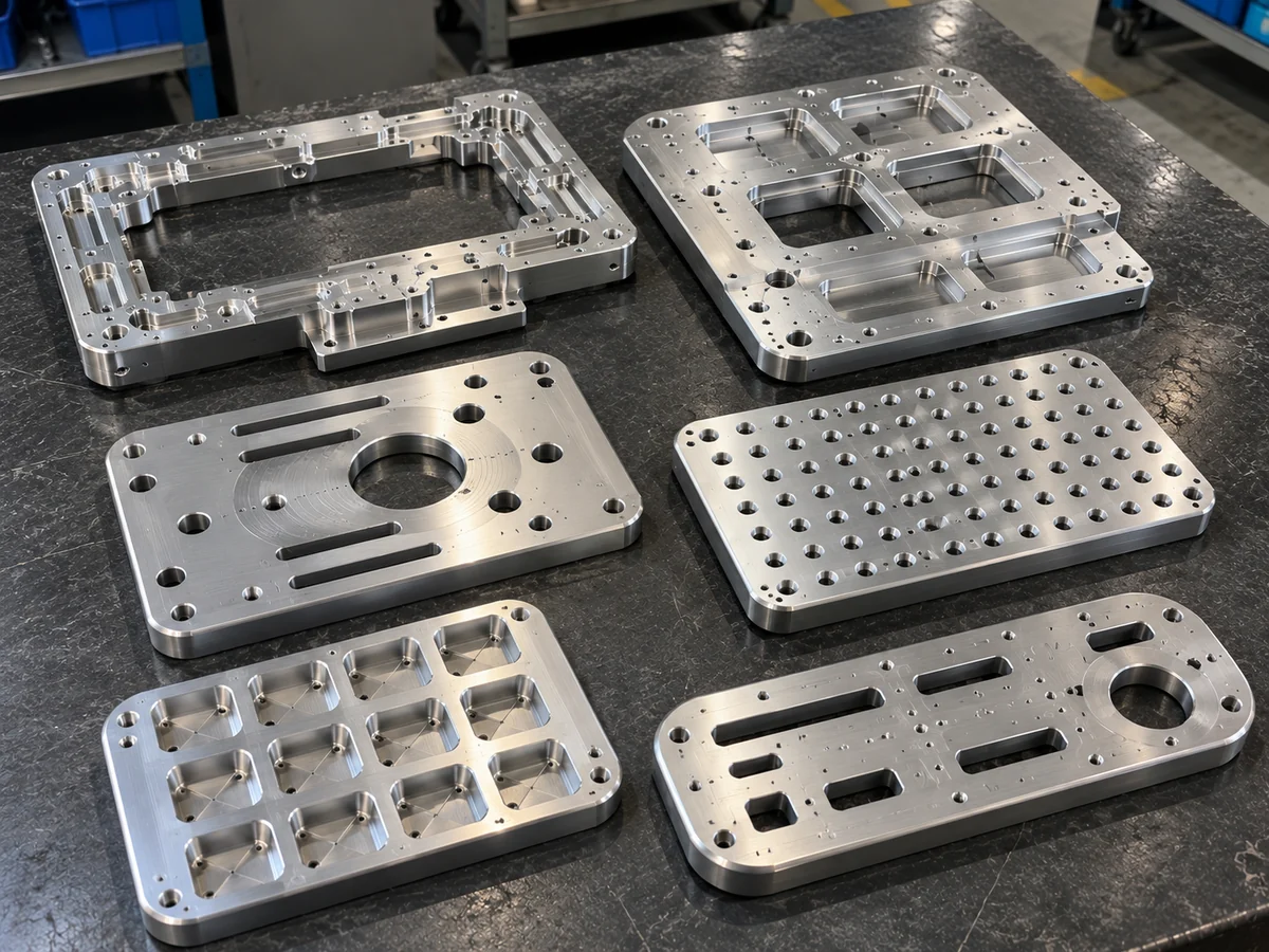
A catalogue NEMA 23 bracket or a listed F05-to-F07 mounting kit is cheaper when it puts the part where you need it; a plate is made when the two patterns, the offset, the height or the material are yours.
| You need | From stock? | How it is made |
|---|---|---|
| An L-bracket or plate for one NEMA frame, catalogue pattern | Yes — stock item | Buy it from stock if it puts the motor where you need it — or ask us, we may have it in stock. Standard parts: ask us too — we may have them in stock. |
| A mounting kit for a common valve and actuator pair | Yes — stock item | Buy it from stock from the valve or actuator supplier when the pair is listed; made to order when it is not |
| A plate from your old pattern to your new one | No | Both patterns measured from one corner, milled in one set-up so they stay true to each other |
| A plate that must centre the part, not just hold it | No | Spigot recess bored to the pilot, or two H7 dowel holes, one round and one slot |
| The part has to sit higher, lower or turned | No | Stepped or pocketed plate, or a riser plate with both patterns |
| A long or loaded plate that flexes in aluminium, or one in a wash-down area | No | Steel S355 or C45, or a thicker 6061 plate; stainless 304 (1.4301) or 316 (1.4404) for wash-down |
Before an adapter plate is cut: fit, the next motor, no drawing, a discontinued plate
Will the adapter plate fit? Checks before you order
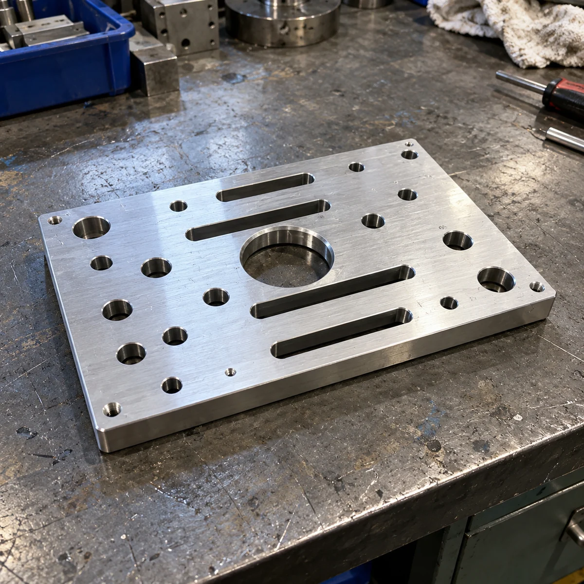
The two patterns are drawn from the same corner, so a hole that is out by 1 mm shows on the approval drawing, not on the machine. A part that must stay aligned is centred by a pilot recess or two dowels; clearance holes alone let it move by up to 1 mm on an M8. Screw heads on the machine side are counterbored so the plate sits flat, and the shaft, the coupling and the cable exit are checked for room before the thickness is fixed.
Same plate, but the next motor is different
A plate drawn for one NEMA 23 motor is redrawn for a NEMA 34 or a servo with a different pilot in a day, because the machine side does not change. A plate first made in 6061 for a test and later wanted in steel for production keeps both patterns and changes the material line.
No drawing of the machine side
Measure the machine's holes from one corner of the mounting face, or measure two neighbouring holes of a circle and multiply by 1.414 for four holes, as in the bolt-circle table. A photo of the face with a ruler in frame shows which holes are tapped and which are through. Posting the old plate or the part is the surest route; the drawing made from it comes back for approval.
The original adapter plate is no longer available
An adapter plate is a drawing, a material and a finish; when the machine builder no longer supplies it, the old plate or the two parts are enough to make a new one from 1 piece, and the drawing is kept for the next machine of the same type.
What an adapter plate costs, and what to send for one
An adapter plate is priced on its size and material, the number of hole sizes, the location features and the finish, and the quote comes within 12 hours with the drawing of both patterns.
| Cost driver | What it means on a machined plate |
|---|---|
| Size and material | A 200 × 150 × 15 mm 6061 plate costs a fraction of the same plate in stainless |
| Number of hole sizes | Two patterns usually mean two or three hole sizes and one or two threads |
| Pilot recess and dowels | A bored recess or reamed dowel holes add a finishing operation each |
| Features on both faces | Counterbores on the machine side and tapped holes on the part side mean two set-ups |
| Tolerance | Hole positions to ±0.01 mm where the parts need it; the rest to ISO 2768-m |
| Finish | Clear or black anodise, blasted, or zinc on steel; threads masked |
| Quantity | 1 plate carries the set-up and the program; a second plate of the same drawing shares both |
| Inspection | A report with both patterns measured, on request |
Send the part's datasheet drawing or its measured pattern, the machine's pattern from one corner, the centring feature, the thickness limit and the quantity; or post both parts and the plate is drawn from them. More on hole types, materials and finishes is on custom machined plates.
Frequently asked questions about adapter plates
Yes, from 1 piece. The plate carries the motor's hole pattern and pilot recess on one side and the machine's holes on the other, measured from the same corner, so the motor bolts on without drilling the machine. For an industrial motor swapped onto an old machine face, the motor adapter rings and plates page covers NEMA C-face, IEC B5 and B14 flanges; stepper and servo plates are covered here.
Both hole patterns measured from one corner or from a common centre, the feature that centres the part (a pilot diameter or two dowels), the room needed for screw heads, the shaft and cables, the load and the thickness limit, and the material. If measuring is awkward, both parts can be posted to us and the plate is drawn from them for your approval.
Measure the centre distance between two neighbouring holes and multiply it by 1.414; for six holes multiply by 2, for eight by 2.613. The centre distance is the outside-edge-to-outside-edge measurement minus one hole diameter. A flange with 50 mm between neighbouring holes of four has a bolt circle of about 70.7 mm.
Four Ø5 mm (0.195 in) through holes on a 47.14 mm (1.856 in) square, around a Ø38.1 mm (1.500 in) pilot, on a face of about 57 mm. A NEMA 17 stepper has four M3 tapped holes on a 31.0 mm square and a Ø22 mm pilot; a NEMA 34 has four Ø5.5 mm holes on a 69.6 mm square and a Ø73 mm pilot.
Yes. An F05 flange has four M6 on a 50 mm circle and an F07 four M8 on a 70 mm circle, so an F05-to-F07 plate carries both circles on one centre line with a recess for the centring spigot. The square or double-D drive between actuator and valve stem is a separate coupling, machined to both stems.
Aluminium 6061 for most motor, sensor and actuator plates; steel where the plate is thin, long or loaded at one end, because steel is about three times stiffer. An aluminium plate needs about 1.44 times the thickness of a steel plate to bend the same amount, so a 10 mm steel plate becomes about 14.5 mm in aluminium.