EKINSUN LTD is a custom parts manufacturer, and crossed helical gears reach us in one recurring situation: the drive needs a specific centre distance or a specific ratio, and the catalogue ladder has nothing that lands on it. This page is about that gear — the arithmetic that decides its tooth count, the hand rule that decides whether the pair will even run, and the two cases where you should buy from stock instead.
Your Centre Distance Picks the Tooth Count — the Catalogue Offers Six
A 45° crossed helical gear has no naturally preferred tooth counts; the catalogue ladder is a stocking decision, not a geometric one. Pitch diameter follows straight from the normal module and the helix angle:
d = mn · z / cos 45° = 1.4142 · mn · z · outside diameter da = d + 2 mn · centre distance a = (d1 + d2) / 2
Run that at module 2 and the ladder becomes obvious — along with its holes. Every stocked size below is reproduced exactly by the formula, which is why the off-catalogue rows are calculated rather than guessed:
| Teeth (z) | Pitch dia. d | Outside dia. da | Stocked at module 2? | Centre distance with a 20T mate |
|---|---|---|---|---|
| 10 | 28.28 mm | 32.28 mm | Yes | 42.43 mm |
| 11 | 31.11 mm | 35.11 mm | No — ladder jumps 10 → 13 | 43.84 mm |
| 12 | 33.94 mm | 37.94 mm | No | 45.25 mm |
| 13 | 36.77 mm | 40.77 mm | Yes | 46.67 mm |
| 14 | 39.60 mm | 43.60 mm | No | 48.08 mm |
| 15 | 42.43 mm | 46.43 mm | Yes | 49.50 mm |
| 16 | 45.25 mm | 49.25 mm | No — widest hole starts here | 50.91 mm |
| 18 | 50.91 mm | 54.91 mm | No | 53.74 mm |
| 20 | 56.57 mm | 60.57 mm | Yes | 56.57 mm |
| 22 | 62.23 mm | 66.23 mm | No | 59.40 mm |
| 26 | 73.54 mm | 77.54 mm | Yes | 65.05 mm |
| 30 | 84.85 mm | 88.85 mm | Yes | 70.71 mm |
The widest gap sits between 15 and 20 teeth. Four tooth counts are missing there, and because every tooth moves the centre distance by 1.41 mm at module 2, that single jump puts 7.07 mm of centre distance out of reach if you are buying from stock. A housing already bored at 51 mm centres has no catalogue answer; a 16-tooth gear against a 20-tooth mate gives 50.91 mm and it fits.
And the ladder is not the same ladder everywhere. The six sizes above are one common stocking pattern; HPC Europe’s crossed-axis line at module 2 carries 25 and 26 teeth, where that pattern has 26 but no 25. Every supplier stocks its own subset, so a size you found in one catalogue may simply not exist in the next — which is the practical reason to check the arithmetic before you check availability. The formula holds across all of them: HPC lists 25 teeth at 70.71 mm pitch and 74.71 mm outside diameter, and 26 teeth at 73.54 mm and 77.54 mm, exactly what d = m·z/cos 45° returns.
Same Hand or Opposite — the Error That Scraps Both Gears
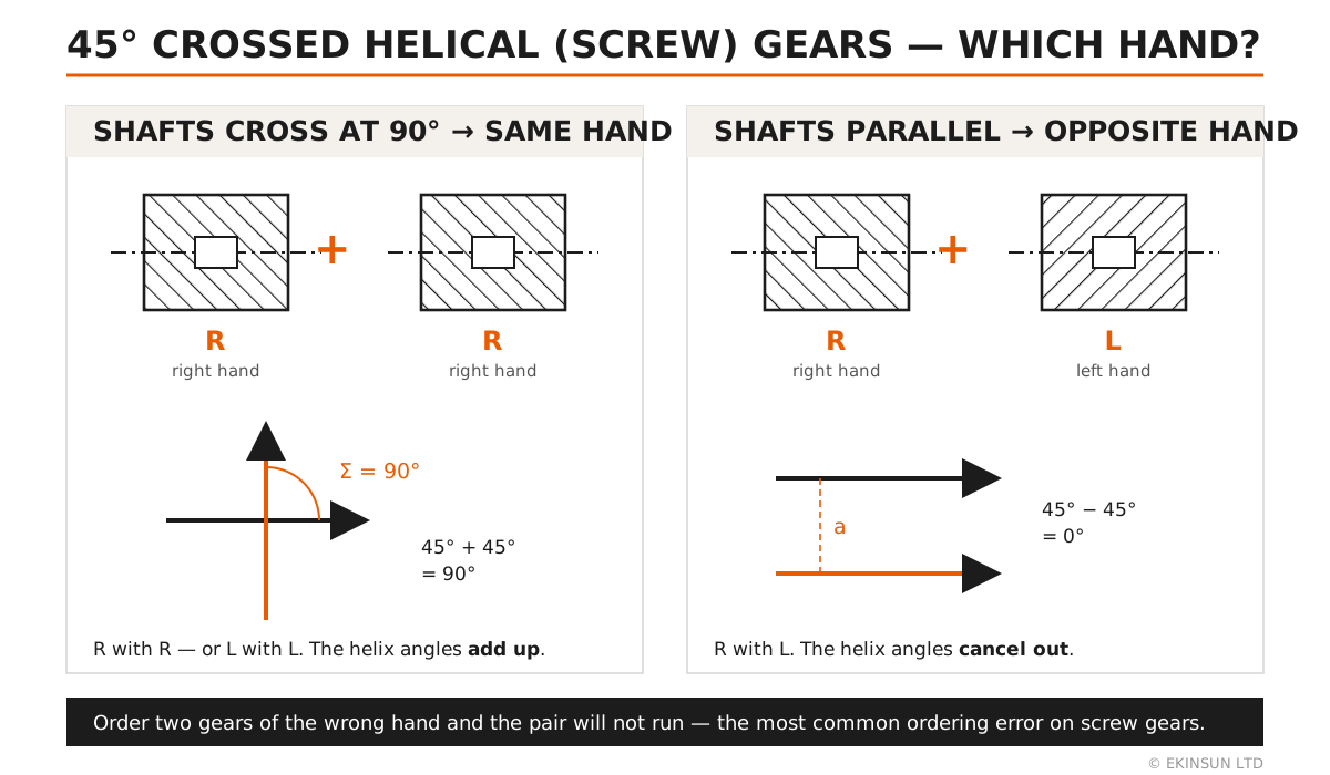
The shaft angle is set by the two helix angles, and how they combine depends on hand. Same hand and the angles add; opposite hand and they cancel. For a pair of 45° gears that produces exactly two useful outcomes:
- Crossed shafts at 90° — 45° + 45° = 90°, so both gears must be the same hand: R with R, or L with L. This is the normal use of a screw gear.
- Parallel shafts — 45° − 45° = 0°, so the gears must be opposite hands: R with L. The same parts, used as an ordinary helical pair.
It reads as a detail and it is the single most common ordering mistake on these gears, because the instinct carried over from ordinary parallel-shaft helical gears — “one left, one right” — is exactly backwards for the crossed case.
“AGMA 10” Means Two Different Things — Here Is the One We Cut To
A gear quality number is meaningless without the standard that issued it, and AGMA has published two systems that run in opposite directions. Under AGMA 2000-A88 the quality number Qv runs from 3 to 15 and a higher number is finer. Under the later AGMA 2015-1-A01 the numbering was aligned with ISO, where a lower number is finer. So “AGMA 10” is a good grade under one standard and a coarse one under the other.
| Grade | AGMA 2000-A88 | ISO 1328-1 | DIN 3962 | JIS B 1702-1 | Where it turns up |
|---|---|---|---|---|---|
| What we cut to | Q10 | grade 7 | grade 7 | grade 7 | Hobbed, then finished after hardening |
| One grade coarser | Q9 | grade 8 | grade 8 | grade 8 | Typical stocked screw gear, hardened |
| Two grades coarser | Q8 | grade 9 | grade 9 | grade 9 | Budget stocked grade and most nylon gears |
The crosswalk above is approximate by nature: the standards do not measure the same set of tooth elements, so no exact equivalence exists and anyone publishing one to the decimal is overselling. Read it as one grade of margin, not as a conversion.
The honest condition on Q10. A tooth cut to Q10 and then through-hardened does not stay at Q10 — heat treatment moves it. Holding Q10 on a hardened gear means a finishing operation after hardening, and that is a separate line on the quote rather than something bundled in silently. If the drive does not need it, hobbed-and-induction-hardened at Q9 is the cheaper and honest answer.
45# Steel, S45C, C45 — One Steel, Three Standards
The default material for these gears is a 0.45 % carbon steel that carries a different name in every market, and they are interchangeable for this part. Quoting the right designation to your inspector matters more than the steel itself:
| Material | Designations | Condition on the gear | Use it? |
|---|---|---|---|
| Carbon steel, 0.45 % C | EN 10083-2 C45 (1.0503) · JIS G4051 S45C · GB/T 699 45# · AISI 1045 | Teeth induction hardened to HRC40–55, black oxide finish | Standard |
| C45E quenched & tempered | EN 10083-2 C45E (1.1191) | Through-hardened core where the drive shocks or reverses | Step up |
| Stainless 304 | EN 10088 1.4301 · JIS SUS304 · AISI 304 | Unhardened. Washdown, food and damp environments — accept shorter tooth life | Yes |
| MC nylon / cast PA6 | — | Quiet, self-lubricating, light load; run it against a steel driver, not against another nylon gear | Yes |
| Tin bronze | CuSn12 · C90700 | The classic answer to sliding wear: bronze wheel against a hardened steel driver, exactly as in a worm set | Where wear governs |
| Aluminium 6061-T6 | EN AW-6061 | Crossed teeth slide rather than roll, and aluminium galls under that contact | No — hub and blanks only |
| Aluminium 7075-T6 | EN AW-7075 | Stronger than 6061 but no better against galling; the failure mode is surface, not strength | No — we will say so |
Background on the steels and the stainless sits on the carbon steel machining and 304 stainless machining pages, and the aluminium comparison behind those two “no” rows is set out under 6061 vs 7075.
What a Screw Gear Cannot Do — Read This Before Ordering
Crossed helical gears mesh at a point, not along a line. Contact is a single point that slides fast, so rated capacity is a small fraction of a parallel-axis helical pair of the same diameter, and wear — not tooth breakage — ends their life. That is inherent to the geometry and no amount of hardening or precision changes it. They are correct for light drives, timing links, instrument movements and feed take-offs across 90°. If your drive has to carry real torque across right-angled shafts, the right parts are a bevel set or a worm and wheel, and we would rather tell you that than sell you a screw gear that wears out.
What the Catalogue Does Well — and Where It Stops
| What you need | Off the shelf? | The honest route |
|---|---|---|
| Ladder tooth count, ladder bore — module 2, 20T, R hand, 15 mm bore | Yes — stocked deep by gear catalogues | Buy stock. No one-off competes with a stocked screw gear on price, and we will not pretend otherwise |
| Stocked size, bore reamed out a little | Stock gear plus a bore operation | Cheaper as a modification than as a new gear — ask for that, not for a fresh part |
| 11, 12, 14, 16, 18 or 22 teeth — ratio or centre distance lands off the ladder | Not stocked at any module | Hobbed to the tooth count you calculated, from 1 piece |
| Bore outside the catalogue range — e.g. 8 mm through a 20T, or 35 mm through a 26T | Each size has a fixed bore window | Bore, keyway and set-screw flats cut to your shaft, hub proportions adjusted to suit |
| Finer than the stocked grade — AGMA 2000-A88 Q10 rather than JIS grade 8 | Stock is supplied at grade 8 or 9 | Finishing pass after hardening, priced as its own line |
| A replacement for a gear with no catalogue at all | Machine long orphaned | Module, hand and tooth count recovered from the old gear — see copying from a sample |
| Bronze or an odd hub form — extended boss, flange, second bore | Catalogue hubs are fixed | Machined as one part rather than a stock gear plus an adapter |
“I need a 45° screw gear pair to sit at 51 mm centres, module 2. Nearest catalogue combination puts me at 49.5 or 56.6 and I cannot move the housing bores. Both shafts are 12 mm with a 4 mm keyway. Can you cut a 16-tooth and a 20-tooth, both right hand?”
That is a complete enquiry. Everything needed is in it: module, helix angle, the centre distance that cannot move, the shaft and keyway, and the hand — right for both, because the shafts cross. The reply confirms 50.91 mm from a 16T against a 20T, asks which gear drives and roughly what torque, and proposes hardened C45 with the finishing pass only if the duty warrants it. Work like this sits beside the rest of the drive-train jobs here: custom spur gears, gearbox parts and machined shafts.
Screw Gear, Spiral Gear, Crossed Helical Gear — Same Part
Three names describe one component, which is the main reason these gears are hard to find. KHK catalogues them as screw gears, MISUMI as spiral gears, and standards and textbooks as crossed helical or crossed-axis helical gears. Chinese suppliers list them by the parameters instead — module, tooth count, hand and helix angle. All of it means an ordinary involute helical gear, usually cut at 45°, running on shafts that neither meet nor run parallel. If you searched three names and found three different-looking products, they were the same gear.
Custom Helical Gears Beyond the Crossed Pair
A crossed pair is one job on the hobber, and the rest of the drive train is cut on the same machines. EKINSUN works as a custom gear manufacturer rather than a screw-gear specialist, so the parts either side of the pair are normal orders here:
- Parallel-shaft helical gears — the ordinary case, cut at a 15° to 20° helix instead of 45°, where quiet running and load sharing matter more than a right-angle take-off. Same tooth form, different helix, opposite hands
- Spur gears and pinions, module 0.5 to 8, rebuilt from a sample when the machine has no catalogue left — custom spur gears
- Worm and wheel sets, which is the honest answer whenever a screw gear cannot carry the torque — custom worm gears
- Gear racks cut to mesh with a pinion that survived — gear racks matched to your pinion
- Gear shafts, cluster gears and finished blanks — teeth and shaft as one part, or a blank left ready for your own gear cutting
Ordering any of them works the same way: send the numbers, send the old part, or send a photo with a caliper in the frame. Gear cutting from a drawing is routine; gear cutting with no drawing at all is equally routine, and it is most of what arrives here.
How to Order
- The four numbers that define it: normal module, tooth count, helix angle and hand. Module 2, 45° is the common case here; module 1.0, 1.5, 2.5 and 3.0 are cut the same way
- The centre distance you cannot move — it is what decides the tooth counts, and it is the figure most enquiries leave out
- The shaft: diameter and tolerance, keyway width, or set-screw flats. Bores are cut to H7 unless you specify otherwise
- The shaft layout — crossed at 90° or parallel. We derive the hand from this and put it on the drawing so it cannot be misread
- Or send the old gear. Tooth count, module, hand and helix angle are all recoverable from a worn sample, and it comes back with the new one
A dimensioned approval drawing comes before any metal is cut, and it names the hand of each gear explicitly. Quote in 12 hours; production typically 7–15 days after approval. There is no tooling charge, which is why a single replacement gear is a normal order here rather than an exception.
Will it mesh? Screw gear checks before you order
At module 2 and 45° a crossed helical gear's pitch diameter is 2 × teeth ÷ cos 45°, so a 10-tooth gear is 28.28 mm and a 16-tooth is 45.25 mm, and the centre distance is half the sum of the two. That is why a 45 mm centre distance does not land on whole teeth: 16 + 16 gives 45.25 mm, 15 + 17 the same, and the only ways to hit 45.00 are a 0.25 mm shim on the centre or a pair cut to a slightly corrected module. For shafts at 90°, both gears are the same hand — a right-hand gear against a left-hand one will not mesh at 90° at all.
What do I need for a 45 mm centre distance at module 2?
Either two 16-tooth gears with the centre set to 45.25 mm, or the pair cut to the module that puts 32 teeth on 45.00 mm exactly, with the hand stated, the bore and keyway to each shaft, and the steel or bronze pairing chosen for the load. Send the centre distance you actually have; we pick the tooth count and say which of the two answers it is.
Same gear, but bronze, 12 teeth, or a keyed bore
Tin bronze against a steel mate for a sliding drive, a tooth count the catalogue skips, a keyway or set-screw bore, or a face width to suit an old gearbox — each is a variant of the same drawing, one piece and up, quoted in 12 hours.
Frequently Asked Questions
It depends on how the shafts run, and it is the error that scraps most screw-gear orders. The shaft angle equals the sum of the two helix angles when both gears have the same hand, and the difference when they are opposite. Two 45° gears of the same hand therefore give 45° + 45° = 90°, which is the crossed-shaft case. The same two gears with opposite hands give 45° − 45° = 0°, which is parallel shafts. So: crossed at 90° means R with R, or L with L. Parallel means R with L. Tell us the shaft layout and we will state the hand of each gear on the approval drawing.
Because catalogues ladder a fixed set of sizes rather than every tooth count, and each supplier stocks its own subset. One common module 2 pattern at 45° runs 10, 13, 15, 20, 26 and 30 teeth, while HPC Europe's crossed-axis line carries 25 and 26 instead, so a size you found in one catalogue may simply not exist in the next. The geometry itself has no gaps: pitch diameter is d = m·z/cos45°, which gives 28.28 mm at 10 teeth, 31.11 mm at 11, 33.94 mm at 12 and 36.77 mm at 13. The widest hole in the common pattern is between 15 and 20 teeth, where it skips four sizes and leaves a 7.07 mm gap in achievable centre distance. If your centre distance or ratio lands in one of those gaps, the tooth count has to be cut rather than chosen.
AGMA 10 needs its standard named, because two AGMA systems run in opposite directions. Under AGMA 2000-A88 the quality number Qv runs 3 to 15 and higher is more precise, so Q10 is a good grade, roughly ISO 1328 grade 7 and DIN 3962 grade 7. Under the later AGMA 2015-1-A01 the numbers run the ISO way and A10 would be coarse. We cut to AGMA 2000-A88 Q10, which is about one grade finer than the JIS B 1702-1 grade 8 and grade 9 that stocked screw gears are supplied to. One honest condition: on a hardened tooth Q10 only holds if there is a finishing operation after hardening, so we price hardening and finishing as separate lines instead of quietly claiming both.
Far less than its size suggests, and this is geometry rather than quality. Crossed helical gears touch at a point instead of along a line, and the sliding velocity at that point is high, so rated capacity is a small fraction of a parallel-axis helical pair of the same diameter and wear governs life rather than tooth breakage. They are the right choice for light drives, timing links, instrument and feed movements across 90°. If you need to transmit real torque across right-angled shafts, a bevel set or a worm set is the correct answer and we will tell you so rather than sell you a screw gear.
Yes — three names for one part, which is why they are hard to search for. KHK lists them as screw gears, MISUMI as spiral gears, and most textbooks and engineering standards as crossed helical gears or crossed-axis helical gears. All describe ordinary involute helical gears, commonly cut at a 45° helix, running on shafts that neither intersect nor are parallel. A plain helical gear on a parallel shaft is the same tooth form at a smaller helix angle, so the naming difference is about how the gear is used, not how it is made.
EKINSUN — a custom parts manufacturer that hobs module 1.0 to 3.0 screw gears at a 45° helix in any tooth count from 10 to 30, including the off-catalogue 11, 12, 14, 16, 18 and 22, with the bore, keyway and hub cut to the shaft you already have, from 1 piece and quoted in 12 hours. Two honest exceptions: if your size is a catalogue size in a catalogue bore — module 2, 20 teeth, R hand, 15 mm bore, for example — buy it from stock, because no one-off can match that price; and if the drive has to carry real torque, ask us for a worm or bevel set instead.
Get a Quote
Module, tooth count, hand, bore — and the centre distance. Reply in 12 hours.
// In short
- →Ladder size, ladder bore? Buy stock
- →11, 12, 14, 16, 18, 22 teeth? We hob it
- →d = 1.4142 · m · z — at 45°
- →Crossed = same hand. Parallel = opposite
- →From 1 piece, quote in 12 hours
or email: [email protected]