This chart is here because a standard bush is a part we tell people not to order from us: an ISO 4379 size in bronze is on a stockist's shelf for less than we could ever turn it. What reaches us is the bush that is not on the shelf — the housing that has worn oversize so no catalogue d2 is tight any more, the bore between two standard sizes, the flange that has to be thicker than b2, the same geometry in stainless or POM. Use the tables to check whether your bush has a row; if it does not, that is the part we machine from one piece. EKINSUN LTD is a custom parts manufacturer that turns bushings, bushes and sleeves to a drawing, a sketch or a worn sample, in bronze, brass, steel, 304/1.4301 and 316L/1.4404 stainless, 6061 aluminium or plastics.
// ISO 4379 Limit Calculator — pick bore, outside diameter & value
Limits per ISO 286-2. ISO 4379 supplies the bore at E6 and the outside at s6 (r6 above 120 mm); pressed into an H7 housing the bore closes to about position H, grade IT8. The after-press value shown is that H8 band — verify on the assembled part if the fit is critical.
Type C — Cylindrical Sleeve Bush Sizes (mm)
One row per bore. ISO 4379 gives each bore up to three outside diameters (thin, medium and thick wall) and up to three lengths; any d2 combines with any b1. The last column is the bore limit the bush is made to before pressing. Sizes in parentheses in the standard (24, 27, 33, 36 mm) are for special applications and are left out here; the standard continues in the same pattern up to d1 = 200 mm.
| Bore d1 | Outside Ø d2 (options) | Length b1 (options) | Chamfer c1, c2 max (45°) | c2 max (15°) | Bore as supplied (E6) |
|---|---|---|---|---|---|
| 6 | 8 / 10 / 12 | 6 / 10 / — | 0,3 | 1 | 6.020 – 6.028 |
| 8 | 10 / 12 / 14 | 6 / 10 / — | 0,3 | 1 | 8.025 – 8.034 |
| 10 | 12 / 14 / 16 | 6 / 10 / — | 0,3 | 1 | 10.025 – 10.034 |
| 12 | 14 / 16 / 18 | 10 / 15 / 20 | 0,5 | 2 | 12.032 – 12.043 |
| 14 | 16 / 18 / 20 | 10 / 15 / 20 | 0,5 | 2 | 14.032 – 14.043 |
| 15 | 17 / 19 / 21 | 10 / 15 / 20 | 0,5 | 2 | 15.032 – 15.043 |
| 16 | 18 / 20 / 22 | 12 / 15 / 20 | 0,5 | 2 | 16.032 – 16.043 |
| 18 | 20 / 22 / 24 | 12 / 20 / 30 | 0,5 | 2 | 18.032 – 18.043 |
| 20 | 23 / 24 / 26 | 15 / 20 / 30 | 0,5 | 2 | 20.040 – 20.053 |
| 22 | 25 / 26 / 28 | 15 / 20 / 30 | 0,5 | 2 | 22.040 – 22.053 |
| 25 | 28 / 30 / 32 | 20 / 30 / 40 | 0,5 | 2 | 25.040 – 25.053 |
| 28 | 32 / 34 / 36 | 20 / 30 / 40 | 0,5 | 2 | 28.040 – 28.053 |
| 30 | 34 / 36 / 38 | 20 / 30 / 40 | 0,5 | 2 | 30.040 – 30.053 |
| 32 | 36 / 38 / 40 | 20 / 30 / 40 | 0,8 | 3 | 32.050 – 32.066 |
| 35 | 39 / 41 / 45 | 30 / 40 / 50 | 0,8 | 3 | 35.050 – 35.066 |
| 38 | 42 / 45 / 48 | 30 / 40 / 50 | 0,8 | 3 | 38.050 – 38.066 |
| 40 | 44 / 48 / 50 | 30 / 40 / 60 | 0,8 | 3 | 40.050 – 40.066 |
| 42 | 46 / 50 / 52 | 30 / 40 / 60 | 0,8 | 3 | 42.050 – 42.066 |
| 45 | 50 / 53 / 55 | 30 / 40 / 60 | 0,8 | 3 | 45.050 – 45.066 |
| 48 | 53 / 56 / 58 | 40 / 50 / 60 | 0,8 | 3 | 48.050 – 48.066 |
| 50 | 55 / 58 / 60 | 40 / 50 / 60 | 0,8 | 3 | 50.050 – 50.066 |
| 55 | 60 / 63 / 65 | 40 / 50 / 70 | 0,8 | 3 | 55.060 – 55.079 |
| 60 | 65 / 70 / 75 | 40 / 60 / 80 | 0,8 | 3 | 60.060 – 60.079 |
| 65 | 70 / 75 / 80 | 50 / 60 / 80 | 1 | 4 | 65.060 – 65.079 |
| 70 | 75 / 80 / 85 | 50 / 70 / 90 | 1 | 4 | 70.060 – 70.079 |
| 75 | 80 / 85 / 90 | 50 / 70 / 90 | 1 | 4 | 75.060 – 75.079 |
| 80 | 85 / 90 / 95 | 60 / 80 / 100 | 1 | 4 | 80.060 – 80.079 |
| 85 | 90 / 95 / 100 | 60 / 80 / 100 | 1 | 4 | 85.072 – 85.094 |
| 90 | 100 / 105 / 110 | 60 / 80 / 120 | 1 | 4 | 90.072 – 90.094 |
| 95 | 105 / 110 / 115 | 60 / 100 / 120 | 1 | 4 | 95.072 – 95.094 |
| 100 | 110 / 115 / 120 | 80 / 100 / 120 | 1 | 4 | 100.072 – 100.094 |
Reading a row: a 20 mm bore comes as 20 × 23, 20 × 24 or 20 × 26 outside, in 15, 20 or 30 mm lengths — Bush ISO 4379-C 20 × 24 × 20 is the medium wall in the middle length. Which wall you get is set by the housing bore you already have, not by preference.
The row that is not in this table is the job we get. A Norwegian enquiry asked for a pilot bushing 32,025 × 17 × 20 mm in RG7. No catalogue has that outside diameter, and the 0,025 is the point: it is a press fit, so the OD was cut at 32,03–32,04, and because pressing in closes the bore, the 17 mm was left at 17,05–17,08 to ream after fitting. The full reasoning is in the pilot bushing case; the same two-fit logic is what a custom bushing order needs from you: housing bore, shaft diameter, length, material.
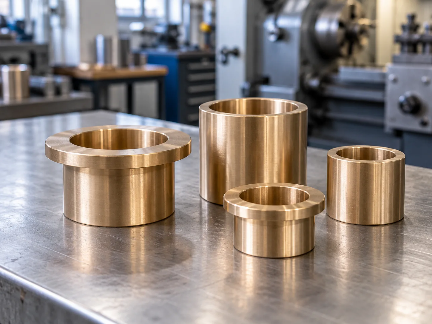
Type F — Flanged Bush Sizes (mm)
A Type F bush is the Type C sleeve with a flange that locates it axially and takes thrust. The standard lists two series: Series 1 is the thin-wall d2 with a thin flange, Series 2 the thick-wall d2 with a heavier flange. Each cell reads d2 / d3 / b2 = outside Ø / flange Ø / flange thickness; b1 is the length under the flange; u is the undercut width at the flange root, which is agreed with the maker, with or without.
| Bore d1 | Series 1 — d2 / d3 / b2 | Series 2 — d2 / d3 / b2 | Length b1 (options) | Undercut u |
|---|---|---|---|---|
| 6 | 8 / 10 / 1 | 12 / 14 / 3 | — / 10 / — | 1 |
| 8 | 10 / 12 / 1 | 14 / 18 / 3 | — / 10 / — | 1 |
| 10 | 12 / 14 / 1 | 16 / 20 / 3 | — / 10 / — | 1 |
| 12 | 14 / 16 / 1 | 18 / 22 / 3 | 10 / 15 / 20 | 1 |
| 14 | 16 / 18 / 1 | 20 / 25 / 3 | 10 / 15 / 20 | 1 |
| 15 | 17 / 19 / 1 | 21 / 27 / 3 | 10 / 15 / 20 | 1 |
| 16 | 18 / 20 / 1 | 22 / 28 / 3 | 12 / 15 / 20 | 1,5 |
| 18 | 20 / 22 / 1 | 24 / 30 / 3 | 12 / 20 / 30 | 1,5 |
| 20 | 23 / 26 / 1,5 | 26 / 32 / 3 | 15 / 20 / 30 | 1,5 |
| 22 | 25 / 28 / 1,5 | 28 / 34 / 3 | 15 / 20 / 30 | 1,5 |
| 25 | 28 / 31 / 1,5 | 32 / 38 / 4 | 20 / 30 / 40 | 1,5 |
| 28 | 32 / 36 / 2 | 36 / 42 / 4 | 20 / 30 / 40 | 1,5 |
| 30 | 34 / 38 / 2 | 38 / 44 / 4 | 20 / 30 / 40 | 2 |
| 32 | 36 / 40 / 2 | 40 / 46 / 4 | 20 / 30 / 40 | 2 |
| 35 | 39 / 43 / 2 | 45 / 50 / 5 | 30 / 40 / 50 | 2 |
| 38 | 42 / 46 / 2 | 48 / 54 / 5 | 30 / 40 / 50 | 2 |
| 40 | 44 / 48 / 2 | 50 / 58 / 5 | 30 / 40 / 60 | 2 |
| 42 | 46 / 50 / 2 | 52 / 60 / 5 | 30 / 40 / 60 | 2 |
| 45 | 50 / 55 / 2,5 | 55 / 63 / 5 | 30 / 40 / 60 | 2 |
| 48 | 53 / 58 / 2,5 | 58 / 66 / 5 | 40 / 50 / 60 | 2 |
| 50 | 55 / 60 / 2,5 | 60 / 68 / 5 | 40 / 50 / 60 | 2 |
| 55 | 60 / 65 / 2,5 | 65 / 73 / 5 | 40 / 50 / 70 | 2 |
| 60 | 65 / 70 / 2,5 | 75 / 83 / 7,5 | 40 / 60 / 80 | 2 |
| 65 | 70 / 75 / 2,5 | 80 / 88 / 7,5 | 50 / 60 / 80 | 2 |
| 70 | 75 / 80 / 2,5 | 85 / 95 / 7,5 | 50 / 70 / 90 | 2 |
| 75 | 80 / 85 / 2,5 | 90 / 100 / 7,5 | 50 / 70 / 90 | 3 |
| 80 | 85 / 90 / 2,5 | 95 / 105 / 7,5 | 60 / 80 / 100 | 3 |
| 85 | 90 / 95 / 2,5 | 100 / 110 / 7,5 | 60 / 80 / 100 | 3 |
| 90 | 100 / 110 / 5 | 110 / 120 / 10 | 60 / 80 / 120 | 3 |
| 95 | 105 / 115 / 5 | 115 / 125 / 10 | 60 / 100 / 120 | 3 |
| 100 | 110 / 120 / 5 | 120 / 130 / 10 | 80 / 100 / 120 | 3 |
Chamfers follow the Type C row for the same bore. Note that the Series 1 outside diameter is the Type C thin wall and Series 2 is the Type C thick wall — so a flanged bush and a sleeve bush for the same housing share a d2, and the flange is the only difference.
Tolerances — Bore, Outside, Housing and Shaft
ISO 4379 fixes the tolerance class of every dimension so that a stock bush pressed into an H7 housing gives a running fit without further machining. The table is the standard's Table 3 with the ISO 286 limits worked out for a 20 mm bore in a 24 mm housing.
| Dimension | Class | Worked example | Why |
|---|---|---|---|
| Bore d1, as supplied | E6 | 20.040 – 20.053 | Oversize on purpose — it closes when pressed |
| Bore d1, after pressing | ≈ H, about IT8 | 20.000 – 20.033 | What the shaft runs in (standard's note a) |
| Outside Ø d2 | s6 (≤120 mm) · r6 (>120 mm) | 24.035 – 24.048 | Interference in the H7 housing holds the bush |
| Housing bore | H7 | 24.000 – 24.021 | The bore you machine in the part |
| Shaft | e7 or g7 | 19.939 – 19.960 (e7) · 19.972 – 19.993 (g7) | Recommended running clearance, by application |
| Flange Ø d3 | d11 | — | Non-functional diameter |
| Length b1 | h13 | — | Non-functional length |
Two exceptions the standard spells out. With ready-made precision ground shafts in tolerance position h, order the bore to D6 instead of E6, which gives about F8 after fitting. And if the bore is to be machined after fitting — the normal route for a line-bored pair of bushes — the supplied bore size is agreed between maker and customer, which is where a custom bushing starts.
Designation and Material — How to Write It on a Drawing
The order string is Bush ISO 4379-C d1 × d2 × b1 - alloy, for example Bush ISO 4379-C 20 × 24 × 20 - CuSn8P: a Type C sleeve, bore 20, outside 24, length 20, in wrought tin bronze CuSn8P to ISO 4382-2. A Y after the size calls for the 15° outside chamfer instead of 45°; Type F adds -F and the series. Materials are copper alloys only — cast to ISO 4382-1, wrought to ISO 4382-2:
| Alloy (ISO 4382) | Form | Also known as | Typical duty |
|---|---|---|---|
| CuSn8P | Wrought tube / bar | Phosphor bronze, PB102, C52100 | Default for machined sleeves, good fatigue and wear |
| CuSn7Zn4Pb7-C | Cast | Rg7 (DE), close to SAE 660 / C93200 | General plain bearings, tolerant of dirty lubrication |
| CuSn12-C | Cast | G-CuSn12, C90800 class | Higher load, slower speed, worm-wheel and press duty |
| CuAl10Ni5Fe4-C | Cast | Aluminium bronze, C95500 class | Shock, high load, seawater |
Which alloy a stockist holds varies by country; if the drawing names one and the certificate matters, order to that name. For a machined bush we supply brass, bronze, steel, 304 / 1.4301, 316L / 1.4404, free-cutting 1.4305, 6061 aluminium or a plastic such as POM — with an EN 10204 3.1 certificate on request.
When the Chart Has No Row — What a Stockist Sells and What Gets Machined
Most bushes that reach us as a drawing or a worn sample are one of these. The middle column is the answer: several of them are still a catalogue part, from a different catalogue.
| The bush you need | Off the shelf? | Who does it |
|---|---|---|
| Standard d1 × d2 × b1 in bronze, Type C or F | Yes | Buy it — a distributor will always be cheaper than any machine shop, and we'll tell you so; or ask us, we may have it in stock |
| Sintered self-lubricating bush (Oilite type) | Yes, ISO 2795 sizes | Sintered-bearing catalogue, not ISO 4379 |
| Housing worn oversize — no standard d2 is tight | No | Bush turned to the measured housing, s6 on the real bore — custom bushing |
| Bore between two standard sizes, or an inch shaft | No | Machined to the shaft, from 1 piece |
| Length not in the b1 list | Rarely | Cut down from stock if shorter; machined if longer or if the chamfer matters |
| Flange thicker than b2, or a flange on both ends | No | Machined; a double flange is a split or two-piece bush |
| Oil grooves, cross-holes, grease nipple thread | No | Machined from a standard blank or from bar |
| Same geometry in stainless, hardened steel or POM | No | Machined — see plastic bushings for POM, nylon and PE-UHMW |
| Bore to be finished after fitting (line-bored pair) | No | Supplied with agreed undersize bore, or the housing sent to us |
Measuring a worn bush for replacement? The bore is the one surface you cannot trust — it wears oval. Measure the housing and the shaft instead; the bush is made to those two. Our note on bearing reverse engineering covers which surface to measure and when a rolling bearing is the cheaper answer.
Quick Answers by Size
20 mm bushing
Type C: d2 23, 24 or 26, b1 15, 20 or 30. Bore as supplied E6 20.040 – 20.053; housing for the 24 mm wall H7 24.000 – 24.021; shaft e7 19.939 – 19.960. Type F Series 1: 23 / 26 / 1,5 · Series 2: 26 / 32 / 3.
25 mm bushing
Type C: d2 28, 30 or 32, b1 20, 30 or 40. Bore E6 25.040 – 25.053; housing for 30 H7 30.000 – 30.021; shaft e7 24.939 – 24.960. Type F Series 2: 32 / 38 / 4.
30 mm bushing
Type C: d2 34, 36 or 38, b1 20, 30 or 40. Bore E6 30.040 – 30.053; housing for 36 H7 36.000 – 36.025; shaft g7 29.972 – 29.993.
40 mm bushing
Type C: d2 44, 48 or 50, b1 30, 40 or 60. Bore E6 40.050 – 40.066; outside 48 s6 48.043 – 48.059; housing 48 H7 48.000 – 48.025.
Related references: the limits and fits chart for the full H7 / s6 / e7 bands, the dowel pin size chart for the pins that locate the same housings, and small machined parts for bushes, spacers and pins under 25 mm.
A bushing held axially by an internal circlip needs a DIN 472 groove in the housing; the groove sizes by bore are in the circlip groove chart.
ISO 4379 / DIN 1850 Bushing FAQ
Bore d1 from 6 to 200 mm, in two types: C is a plain cylindrical sleeve, F has a flange. Each bore has up to three outside diameters d2 and three lengths b1; the chart above lists 6–100 mm, the range stockists carry.
DIN 1850 is the older German sheet series for plain bearing bushes; ISO 4379 is the international standard and its German adoption is DIN ISO 4379. German catalogues still print “DIN 1850 Form C / Form F”, which is the same C = sleeve, F = flanged split. If a drawing quotes DIN 1850, take the d1 × d2 × b1 numbers from the drawing, not from a cross-reference table.
As supplied, d1 is E6 — for a 20 mm bore that is 20.040–20.053 mm. After pressing into an H7 housing the bore closes to tolerance position H, about IT8 (about 20.000–20.033 mm).
d2 is s6 up to 120 mm and r6 above 120 mm, so the bush is an interference fit in an H7 housing bore. A 24 mm outside diameter to s6 measures 24.035–24.048 mm.
The standard recommends e7 or g7, chosen by application — e7 for a looser running fit, g7 for a closer one. With ready-ground h shafts, the bore is ordered to D6 instead, which gives about F8 after fitting.
Type C sleeve, bore 20 mm, outside diameter 24 mm, length 20 mm, made of wrought CuSn8P per ISO 4382-2. A Y after the size means the outside chamfer is 15° instead of 45°.
Cast alloys to ISO 4382-1 or wrought alloys to ISO 4382-2 — CuSn8P (wrought tin bronze), CuSn7Zn4Pb7-C (cast, the German Rg7 and close to US SAE 660 / C93200), CuSn12-C for higher load, or an aluminium bronze such as CuAl10Ni5Fe4-C for shock and marine duty.
EKINSUN LTD is a custom parts manufacturer that machines bushings, bushes and sleeves to your housing and shaft sizes — from one piece, quote in 12 hours, no CAD needed. Send the measured housing bore, the shaft diameter, the length and the material; a worn sample or a hand sketch is enough.
Yes: bores between the standard sizes, outside diameters bored to a housing that has already worn oversize, lengths outside the b1 list, thicker flanges, oil grooves and cross-holes, split bushes, and steel, stainless or plastic instead of bronze. From 1 piece, quote in 12 hours, a worn sample or a sketch is enough.
Bush Not in the Chart?
Worn housing, in-between bore, thicker flange, stainless or POM — we machine bushings from 1 piece. Send the housing and shaft sizes, a sketch, or the worn part.